Bottle processing system

a processing system and bottle technology, applied in the direction of conveyor parts, packaging, liquid handling, etc., can solve the problems of bottle filling machine, bottle filling, bottle bursting, and the whole system to be stopped

Active Publication Date: 2012-08-28
KRONES AG
View PDF8 Cites 1 Cited by
  • Summary
  • Abstract
  • Description
  • Claims
  • Application Information

AI Technical Summary

Benefits of technology

[0008]The present invention is therefore based on the object of allowing in a system having processing units kinematically rigidly coupled to one another the speed of one unit to be changed, whilst the working speed of the other unit may be maintained.
[0011]By interrupting the supply of containers at a first specified point in time it will be achieved that the first processing unit will run idle after a certain time, which means it will not process any more containers. As soon as essentially all of the containers have left the first processing unit, the working speed of the entire system may be reduced.
[0019]A further possible approach would also be to reduce the number of containers supplied to the first processing unit, whereby for example the distances between the containers in the transport direction would be increased. This approach would then make it possible to maintain the working speed in the first processing unit and to reduce at the same time, since effectively a lower amount of containers will reach the second processing unit, their working speed.
[0026]Alternatively, the control device may also cause a specified number of containers to be supplied to the first processing unit and the working speed of the system to be reduced, after the last container has left the first processing unit and before the first of the specified number of containers has reached the second processing unit. Thus, particularly preferably all of the containers will be in the conveying device at the point in time t2.
[0029]Further, a detection device is preferably provided which detects containers in the first processing unit. Thus, it is for example possible to select the point in time t2 depending on an output signal from this detection device, for example to determine by optical means whether all of the containers have left the first processing unit, in order to reduce only then the working speed of the system.
[0031]In a further advantageous embodiment the control device causes the working speed of the system to be adapted, preferably reduced, before the first container of a certain batch or a certain shot is processed in the second processing unit.

Problems solved by technology

Apart from that, however, these buffer means between the units will themselves introduce a certain vulnerability to failures, and in the case of a failure of the buffer means, the entire system will have to be stopped.
During the operation of the above-described system, however, the problem occurs that under certain conditions individual processing units are preferably to be operated at different working speeds, whereas other processing units in the same system need to be operated essentially at the same working speed at all times. For example, it is required for a blowing machine to be operated always at the same working speed, since the intervals during which for example the containers are guided through an oven are precisely determined.
Also, the containers have to be blown after an exactly defined time delay after the heating process.
For example, the problem might occur that a bottle filling machine, in the case of a product change, has to start up at a slow speed to make sure that the product which is initially too warm will not brim over.
Also, the last containers or bottles can usually not be filled at the full power or working speed, since the level of the product they are to be filled with, and thus the flow speed of the product, decreases in the storage (ring) vessel.
This results in the protocol requiring quite a considerable service effort.

Method used


Image

  • Bottle processing system
  • Bottle processing system

Examples


Embodiment Construction

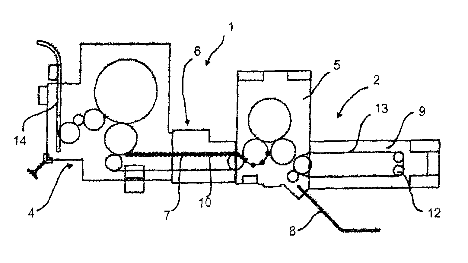
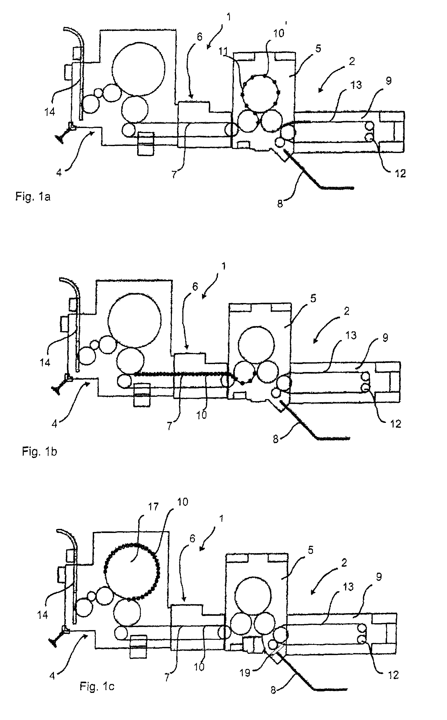
[0037]FIG. 1 shows a system 1 according to the invention in a first operating condition, in which the entire system 1 is operated at a high speed or the regular working speed. What is shown here is the situation in which a plurality of containers 10 have just been arranged in the first processing unit 2, which is a blowing machine, or pass through it. Here, the containers are initially transported by means of a conveying device 13 through an oven 9 and heated therein. The reference numeral 12 relates to a guide roller for the conveyor belt or the conveyor chain 13. The containers 10 are supplied to the system 1 via a supply device 8.

[0038]After an exactly defined heating period, in which the parameters, such as the working speed, for this heating process are precisely established, the containers 10 are blown in the actual blowing device 5, which is also a component of the first processing unit 2, and are brought to their design size. The reference numeral 11 herein relates to the bl...


PUM

PropertyMeasurementUnit
Timeaaaaaaaaaa
Speedaaaaaaaaaa
Areaaaaaaaaaaa

Abstract

The invention relates to a device and a method of processing containers. Herein, a processing system is used in which all of the processing units for the containers are kinematically rigidly coupled to one another. According to the invention, a specified number of containers is supplied to the first processing unit of the system and the working speed of the system is reduced after the last container has left the first processing unit and before the specified number of the first containers has reached the second processing unit.

Description

BACKGROUND OF THE INVENTION[0001]The present invention relates to a method of controlling a system for processing containers and a device for controlling a system for processing containers. The present invention will be described with reference to a system including a blowing machine or a blowing device for plastic bottles and a filling system downstream thereof for filling the containers. However, it is to be noted that the present invention is also applicable to other systems having other processing units for containers.[0002]Such systems which include a blowing machine for containers and a filling machine downstream thereof for the containers, are known from the prior art. In this connection it is also known from the prior art to couple these two processing units kinematically to one another, which means in this case any change of speed in one machine will automatically effect also a change of speed in the other machine. Such systems are the object of the present invention and wi...

Claims


Application Information

Patent Timeline
IPC IPC(8): B67C3/00
CPCB65G43/00B67C7/002B29C49/42B65G2201/0244B67C2003/227B29C49/42802B29C49/42808
Inventor FINGER, DIETER
Owner KRONES AG
Why Eureka
Try Eureka