Vacuum system and method of vacuuming using same

Inactive Publication Date: 2017-03-16
FILTRAR TECH
View PDF0 Cites 5 Cited by
  • Summary
  • Abstract
  • Description
  • Claims
  • Application Information

AI Technical Summary

Benefits of technology

The patent describes a vacuum system for collecting debris from a conveyor belt. The system includes a housing with a suction inlet and an exhaust outlet, a filter assembly, a vibrator, and a debris return mechanism. The vacuum system can be used in a vacuum configuration or a cleaning configuration. In the cleaning configuration, the debris collected in the filter assembly is released onto the conveyor belt. The system also includes a recirculation conduit and a rotor for engaging the debris return mechanism. The technical effects of the vacuum system include improved debris collection and a simplified cleaning process.

Problems solved by technology

In many cases, the material conveyed on the conveyor belt causes dust, debris or the like, derived from the conveyed material, to accumulate on the conveyor belt.
Such debris can be undesirable for a plurality of reasons.
For example, the accumulation of debris on the conveyor belt can cause premature failing of the drive of the conveyor, the conveyor belt, or other components of the conveyor.
Moreover, the debris remaining on the conveyor belt, following a dispensing end thereof may subsequently fall on the floor under the conveyor belt, as the lower portion of the conveyor belt travels above the floor.
However, known vacuum systems for vacuuming a conveyor belt of a conveyor tend to suffer from several drawbacks.
Such collection of the vacuumed material leads to the vacuumed material being removed from the conveyed material, thereby, resulting in an overall loss of material, which can be undesirable.
Moreover, over time, accumulation of the vacuumed material in the vacuum system often leads to degradation of the performance of the vacuum system.
Such a task can be time consuming and cumbersome.

Method used


Image

  • Vacuum system and method of vacuuming using same
  • Vacuum system and method of vacuuming using same
  • Vacuum system and method of vacuuming using same

Examples


Embodiment Construction

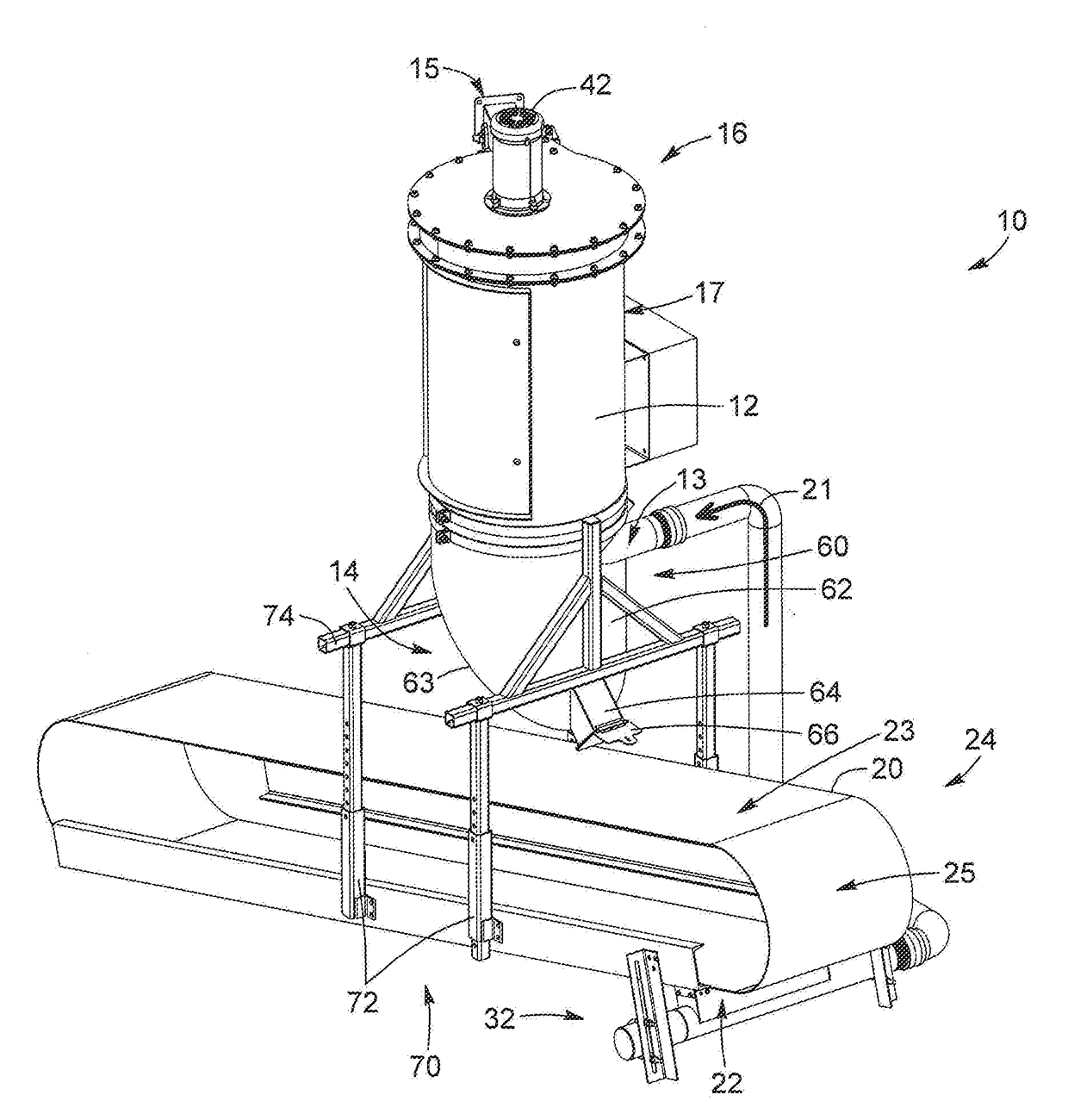
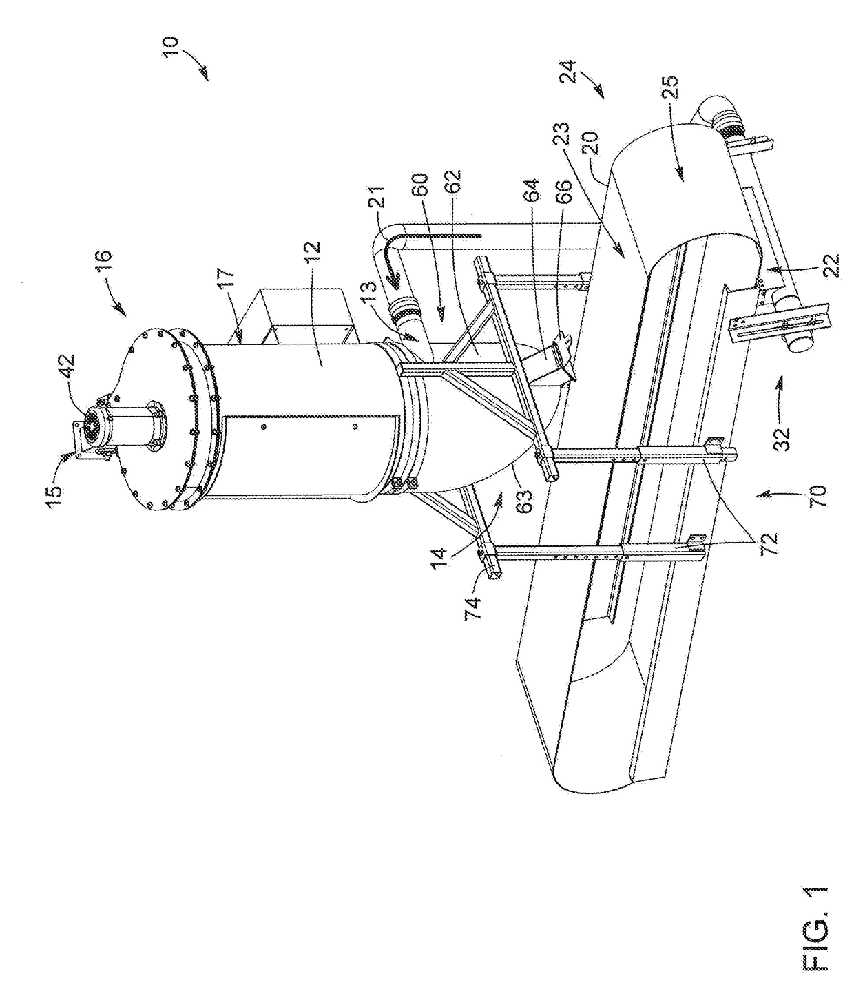
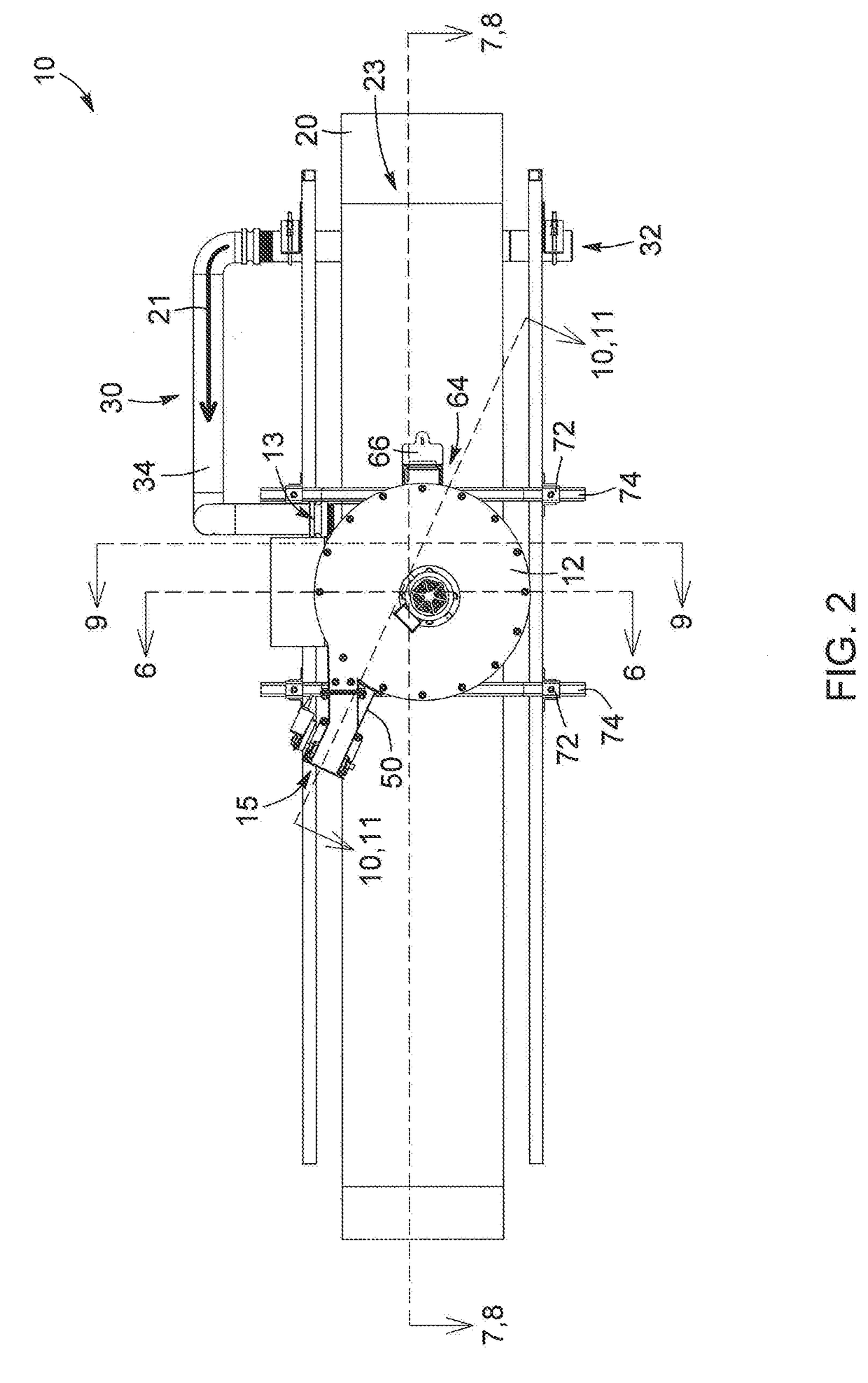
[0033]In the following description, the same numerical references refer to similar elements. The embodiments, geometrical configurations, materials mentioned and / or dimensions shown in the figures or described in the present description are embodiments only, given solely for exemplification purposes.

[0034]Moreover, although the embodiments of the vacuum system for a conveyor belt and corresponding parts thereof consist of certain geometrical configurations as explained and illustrated herein all of these components and geometries are essential and thus should not be taken in their restrictive sense. It is to be understood, as also apparent to a person skilled in the art, that other suitable components and cooperation thereinbetween, as well as other suitable geometrical configurations, may be used for the vacuum system for a conveyor belt, as will be briefly explained herein and as can be easily inferred herefrom by a person skilled in the art. Moreover, it will be appreciated that ...


PUM

PropertyMeasurementUnit
Pressureaaaaaaaaaa
Flow rateaaaaaaaaaa
Vacuumaaaaaaaaaa

Abstract

A vacuum system having a housing defining a collection chamber with a filter assembly mounted therein. The housing has a suction inlet and an exhaust port defined therein and in gas communication through the filter assembly. The vacuum system also includes a suction device having a motor operatively connected to a suction fan configured to generate a gas flow in the housing. The vacuum system also includes a rotor configured to engage the filter assembly in vibration upon rotation of the rotor. The vacuum system also includes a recirculation conduit having a valve configurable in a vacuum configuration preventing the gas flow from flowing through the recirculation conduit and a cleaning configuration allowing at least a portion of the gas flow to flow through the recirculation conduit to engage the rotor in rotation. A method of vacuuming using the vacuum system is also provided.

Description

CROSS-REFERENCE TO RELATED APPLICATIONS[0001]This application claims priority under 35USC §119(e) of US provisional patent application 61 / 947,069 filed on Mar. 3, 2014, the specification of which is hereby incorporated by reference.FIELD OF THE INVENTION[0002]The present invention relates to the field of vacuum systems. More particularly, it relates to a vacuum system configured to vacuum a section of a conveyor belt and return the vacuumed product on the conveyor belt, and to a method of vacuuming a section of a conveyor belt using same.BACKGROUND[0003]Conveyors having a conveyor belt (or transport belt) are well known to move different materials, for example and without being limitative, in a factory, a plant or other industrial facility. In many cases, the material conveyed on the conveyor belt causes dust, debris or the like, derived from the conveyed material, to accumulate on the conveyor belt. Such debris can be undesirable for a plurality of reasons. For example, the accumul...

Claims


Application Information

Patent Timeline
IPC IPC(8): B65G45/10B01D46/00B65G45/22B01D46/02B65B35/00B65G15/00
CPCB65G45/10B65B35/00B65G15/00B01D2279/55B01D46/02B01D46/0075B65G45/22B08B5/046B08B7/02B08B5/04B01D46/76B01D35/16
Inventor TURCOTTE, JEAN-FRANCOIS
Owner FILTRAR TECH
Why Eureka
Try Eureka