Fabric containing a conductive yarn and apparatus for making the same

a technology of conductive yarn and fabric, which is applied in the direction of yarn, textiles and paper, etc., can solve the problems of affecting the quality of conductive yarn, and consuming a large amount of electricity and time to raise the temperature of air in space, so as to reduce the power consumption of conductive yarn of the present invention

Inactive Publication Date: 2017-03-16
APOLLO SUN GLOBAL
View PDF2 Cites 1 Cited by
  • Summary
  • Abstract
  • Description
  • Claims
  • Application Information

AI Technical Summary

Benefits of technology

[0019]According to the above description and embodiments, the conductive yarn and the apparatus for making the same of the present invention have the advantages as following:
[0020]1. The apparatus for making a conductive yarn of the present invention exerts an upward pull on the non-conductive core thread for winding the fine metal thread around the non-conductive core thread to form the conductive yarn of the present invention. The conductive yarn of the present is not easy to be broken and is soft and flexible.
[0021]2. When the fine metal thread wound around the core thread in the spiral form is conducted with electricity to generate heat, the conductive yarn of the present invention has well elasticity for thermal expansion and contraction.
[0023]4. Compared with conventional heaters, the power consumption of the conductive yarn of the present invention is reduced by more than 45%.

Problems solved by technology

In addition, hot air moves upward so people could not feel warm immediately, which result in taking larger amount of electricity and time to raise the temperature of the air in the space to a certain degree.
Moreover, the air in the space is dry, accompanying with thundering noises, due to blowing and flowing of hot air.

Method used


Image

  • Fabric containing a conductive yarn and apparatus for making the same
  • Fabric containing a conductive yarn and apparatus for making the same
  • Fabric containing a conductive yarn and apparatus for making the same

Examples


Embodiment Construction

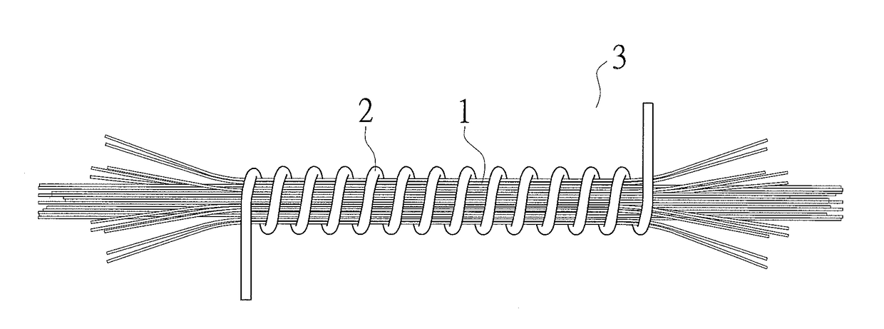
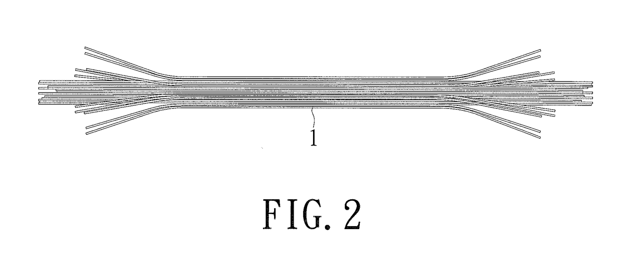
[0030]FIG. 2 to FIG. 4 show schematic views of a core thread, a fine metal thread, and a conductive yarn respectively according to the embodiment of the present invention. A conductive yarn comprises a non-conductive core thread 1 and a fine metal thread 2 wound around the surface of the core thread 1. The non-conductive core thread 1 is made of a plurality of fibers. The fine metal thread 2 is conductive and made of gold, silver, copper, tungsten, and molybdenum microfilament etc., for example. The diameter of the fine metal thread 2 ranges from 0.02 to 0.12 m / m. The fine metal thread 2 is guided by an apparatus to wind around the surface of the core thread 1 in a spiral form so as to form an elastic and flexible conductive yarn 3.

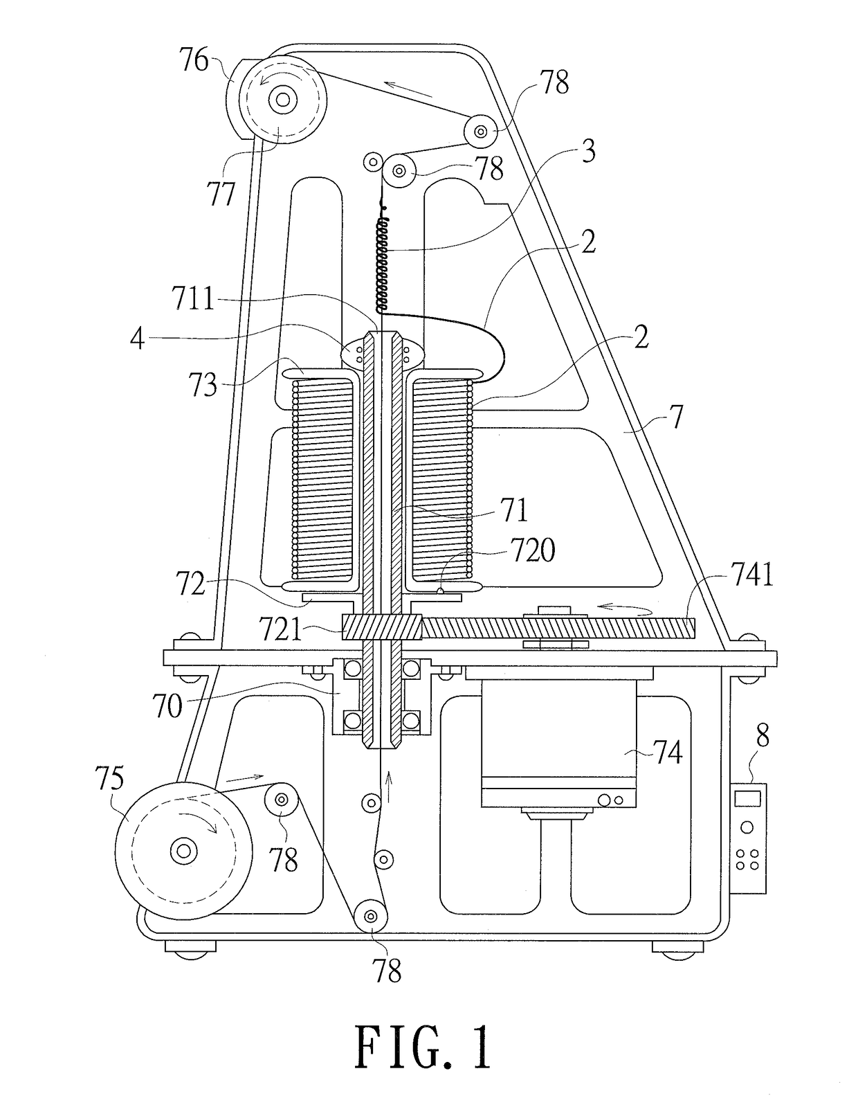
[0031]The apparatus for making the conductive yarn according to the embodiment of the present invention is shown in FIG. 1. The apparatus comprises a base station 7, an axle seat 70, an axle 71, a base 72, a turning wheel 721, a spool 73, a first power so...


PUM

PropertyMeasurementUnit
temperatureaaaaaaaaaa
conductiveaaaaaaaaaa
non-conductiveaaaaaaaaaa

Abstract

A fabric and an apparatus for making the same are disclosed. A conductive yarn has a non-conductive core thread and a fine metal thread wound around the surface of the non-conductive core thread. The fine metal thread is guided by an apparatus to wind around the surface of the non-conductive core thread in a spiral form. The apparatus has a base station, an axle on the base station, and a spool set on the axle for twisting the fine metal thread. The core thread passes through the center of the axle, and the axle is driven by a power to drive the spool to rotate, thuds winding the fine metal thread around the surface of the non-conductive core thread so as to form an elastic and flexible conductive yarn.

Description

RELATED APPLICATIONS[0001]This application is a Divisional patent application of co-pending application Ser. No. 14 / 547,290, filed on 19 Nov. 2014, now pending. The entire disclosure of the prior application, Ser. No. 14 / 547,290 is considered a part of the disclosure of the accompanying Divisional application and is hereby incorporated by reference.CROSS REFERENCE TO RELATED APPLICATION[0002]This application claims the benefits from U.S. Provisional Application No. 61 / 965,616, filed on Feb. 3, 2014, the subject matter of which is incorporated herein by reference.BACKGROUND OF THE INVENTION[0003]Field of the Invention[0004]The present invention relates a fabric having a conductive yarn and an apparatus for making the same. More particularly, a fine metal thread is perfectly wound around a core thread in a spiral form via an apparatus to form a conductive yarn capable of generating heat.[0005]Description of Related Art[0006]The conventional heating equipment generates heat by electric...

Claims


Application Information

Patent Timeline
Patent Type & Authority Applications(United States)
IPC IPC(8): D02G3/12D02G3/44D02G3/38
CPCD02G3/12D02G3/441D02G3/385
Inventor CHI-HSUEH, RICHARD
Owner APOLLO SUN GLOBAL
Why Eureka
Try Eureka