Cooling device and cooling method for engine

a cooling device and engine technology, applied in the direction of control devices for cooling apparatus, fail safe, liquid cooling, etc., can solve the problems of delay in resolving the blockage in the coolant circuit, multi-way valve inoperable, blockage in the circulation of coolant immediately after the engine, etc., to reduce the maximum pressure, shorten the time, and reduce the pressure resistance performance of each part of the coolant circuit

Active Publication Date: 2017-03-16
TOYOTA JIDOSHA KK
View PDF11 Cites 12 Cited by
  • Summary
  • Abstract
  • Description
  • Claims
  • Application Information

AI Technical Summary

Benefits of technology

[0009]The present disclosure provides a cooling device and a cooling method for an engine that suppress pressure rise inside a coolant circuit due to freezing of a coolant.
[0011]When the multiway valve is controlled so as to open at least one of the discharge ports and the ignition switch is turned off (hereinafter termed as IG turn-off operation), at least one of the discharge ports of the multiway valve is open when the ignition switch is turned on (hereinafter termed as IG turn-on operation). Accordingly, the possibility that all the discharge ports of the multiway valve may be closed when the coolant circuit is frozen inside can be eliminated. As a result, it is possible to estimate a shorter time to be taken to resolve a blockage in the coolant circuit due to freezing, and in turn to estimate a lower maximum pressure inside the coolant circuit when a blockage due to a frozen coolant occurs. Thus, the pressure resistance performance required of each part of the coolant circuit can be lowered.
[0012]However, if the radiator port is open when IG turn-on operation is performed, the coolant may flow into the radiator and refreeze by being cooled in the radiator. Moreover, engine warm-up is delayed as the coolant cooled in the radiator reflows into the engine. In this respect, the above engine cooling device is configured to open the discharge ports other than the radiator port when IG turn-off operation is performed. Accordingly, refreezing of the coolant and delayed warm-up as described above can be avoided. Thus, according to the above engine cooling device, it is possible to favorably suppress pressure rise inside the coolant circuit due to freezing of the coolant.
[0015]By contrast, when the outside air temperature is high, heating is not likely to be used after engine restart. In a case where the heating is not used after engine is restarted, leaving the heater port open when IG turn-off operation causes the coolant to be supplied to the heater core after engine restart so that part of engine heat transferred to the coolant is wasted through heat dissipation at the heater core. For this reason, the multiway valve is controlled so as to close the heater port along with the radiator port and open the third discharge port at the time of IG turn-off operation if the outside air temperature is high, so that engine heat can be utilized more efficiently.

Problems solved by technology

Under extremely low temperature conditions, the coolant inside the coolant circuit freezes during an off-time of the ignition switch when the engine is stopped and the circulation of the coolant is stopped, which may result in a blockage in the circulation of the coolant immediately after engine start.
In that case, the coolant inside the multiway valve may also freeze and make the multiway valve inoperable.
If the multiway valve becomes inoperable with all the discharge ports closed while the coolant circuit is frozen inside, the coolant warmed inside the engine no longer flows toward the downstream side from the multiway valve, which results in a delay in resolving the blockage in the coolant circuit due to freezing.
Then, the pressure in the coolant circuit on the upstream side from the blocked position rises all the more significantly due to that delay.
As a result, more expensive parts having higher pressure resistance performance are required, which may lead to an increase in manufacturing cost of the engine cooling device.

Method used


Image

  • Cooling device and cooling method for engine
  • Cooling device and cooling method for engine
  • Cooling device and cooling method for engine

Examples


Embodiment Construction

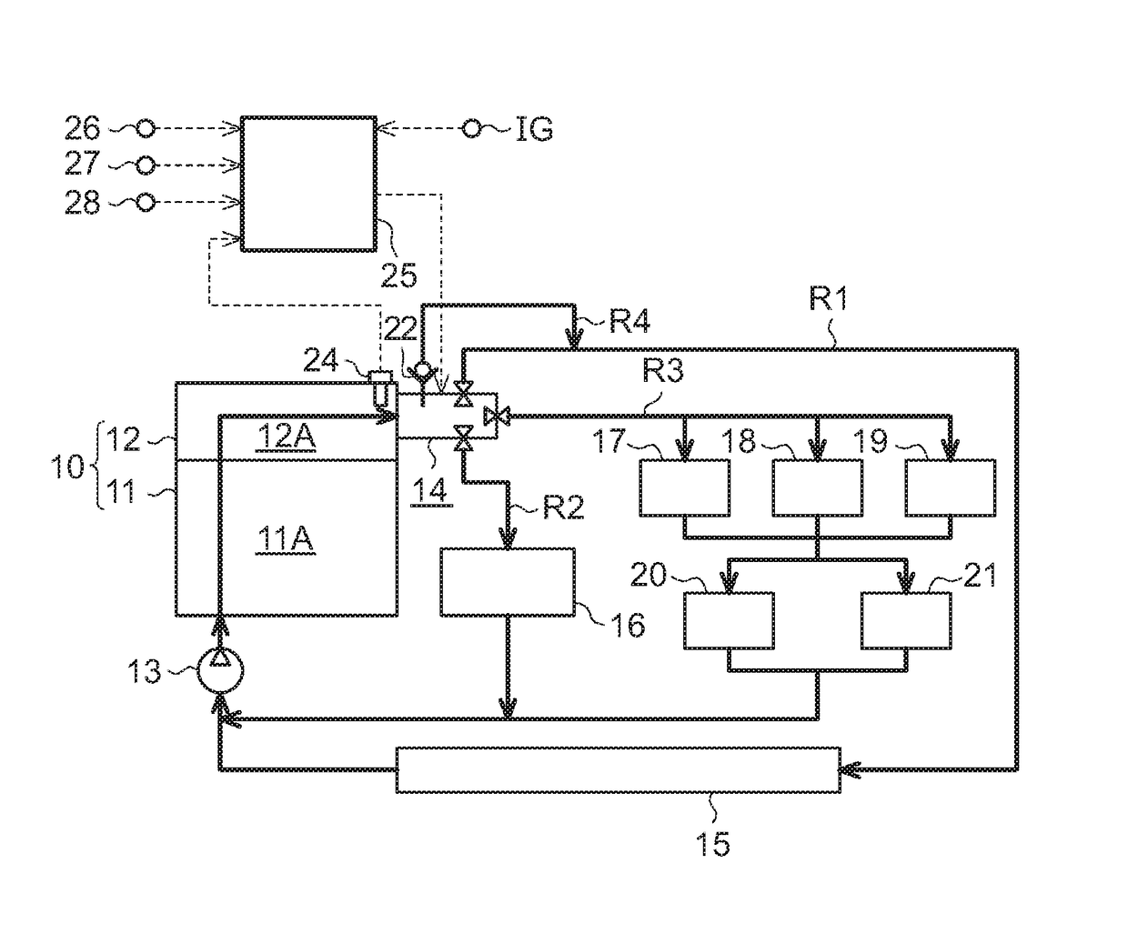
[0027]In the following, one embodiment of an engine cooling device will be described in detail with reference to FIG. 1 to FIG. 8. First, the configuration of a coolant circuit through which a coolant for cooling an engine flows in the engine cooling device of this embodiment will be described with reference to FIG. 1.

[0028]As shown in FIG. 1, water jackets 11A, 12A that constitute a part of the coolant circuit are respectively provided inside a cylinder block 11 and a cylinder head 12 of an engine 10. A coolant pump 13 that circulates the coolant through the coolant circuit is provided in the coolant circuit on the upstream side from the water jackets 11A, 12A. The coolant discharged by the coolant pump 13 is introduced into the water jackets 11A, 12A. The water jacket 12A of the cylinder head 12 is provided with an outlet coolant temperature sensor 24 that detects the temperature of the coolant immediately before flowing out of the water jacket 12A (outlet coolant temperature TO)....


PUM


Abstract

A cooling device for an engine includes a radiator route passing through a radiator, that are merged together after being branched on the downstream side from the inside of the engine in a coolant circuit configured to allow a coolant to flow from a pump through the inside of the engine and return to the pump. An at-stop control section provided in the cooling device controls a multiway valve that has three discharge ports, including a radiator port connected to the radiator route, so as to close the radiator port and open at least one of the other discharge ports when an ignition switch is turned off.

Description

INCORPORATION BY REFERENCE[0001]The disclosure of Japanese Patent Application No. 2015-182045 filed on Sep. 15, 2015 including the specification, drawings and abstract is incorporated herein by reference in its entirety.BACKGROUND OF THE DISCLOSURE[0002]1. Field of the Disclosure[0003]The present disclosure relates to a cooling device and a cooling method for an engine.[0004]2. Description of Related Art[0005]Japanese Patent Application Publication No. 2014-201224 discloses an engine cooling device in which a coolant circuit that circulates a coolant through the inside of the engine is provided with a plurality of routes, including a radiator route passing through a radiator, and a multiway valve is provided at a branching position of these routes. The multiway valve has a plurality of discharge ports that discharge a coolant respectively to the plurality of routes, and switches the routes for the coolant to flow through by switching the open and closed states of the discharge ports...

Claims


Application Information

Patent Timeline
Patent Type & Authority Applications(United States)
IPC IPC(8): F01P7/16F01P3/20F01P5/10
CPCF01P7/165F01P5/10F01P2060/08F01P2007/146F01P2037/00F01P3/20F01P11/20F01P2031/30
Inventor KANEKO, RIHITOTAKAGI, NOBORUTAKAGI, ISAOONODA, HIDETOSHI
Owner TOYOTA JIDOSHA KK
Why Eureka
Try Eureka