
Stand-off weld stud

a weld stud and stand-off technology, which is applied in the direction of screw, load-modified fastener, soldering apparatus, etc., can solve the problem that the weld stud is incapable of transmitting shock loads with sufficient energy to break the fastener

Inactive Publication Date: 2017-03-16
NELSON STUD WELDING
View PDF0 Cites 0 Cited by
  • Summary
  • Abstract
  • Description
  • Claims
  • Application Information

AI Technical Summary

Benefits of technology

The weld stud design described in the patent reduces the chance of failure under external forces, by creating a connection that can absorb shock loads. The reduced diameter portion acts as a limiter, preventing the weld stud from transmitting shock loads with sufficient energy to break the fastener. The ductility zone allows the fastener to stretch and move without engaging the mounting flange, resisting failure during external forces. These features make the weld stud more robust and reliable for high-stress applications.

Problems solved by technology

More specifically, this relationship between the base diameter and threaded diameter establishes a structural strength of the reduced diameter portion that is weaker than a structural strength of the fastener, thus rendering the weld stud incapable of transmitting shock loads with sufficient energy to break the fastener.

Method used


Image

  • Stand-off weld stud
  • Stand-off weld stud
  • Stand-off weld stud

Examples


Embodiment Construction

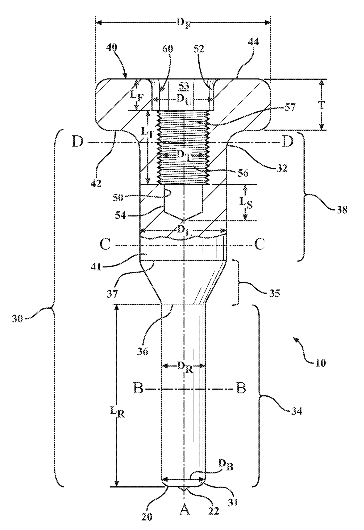
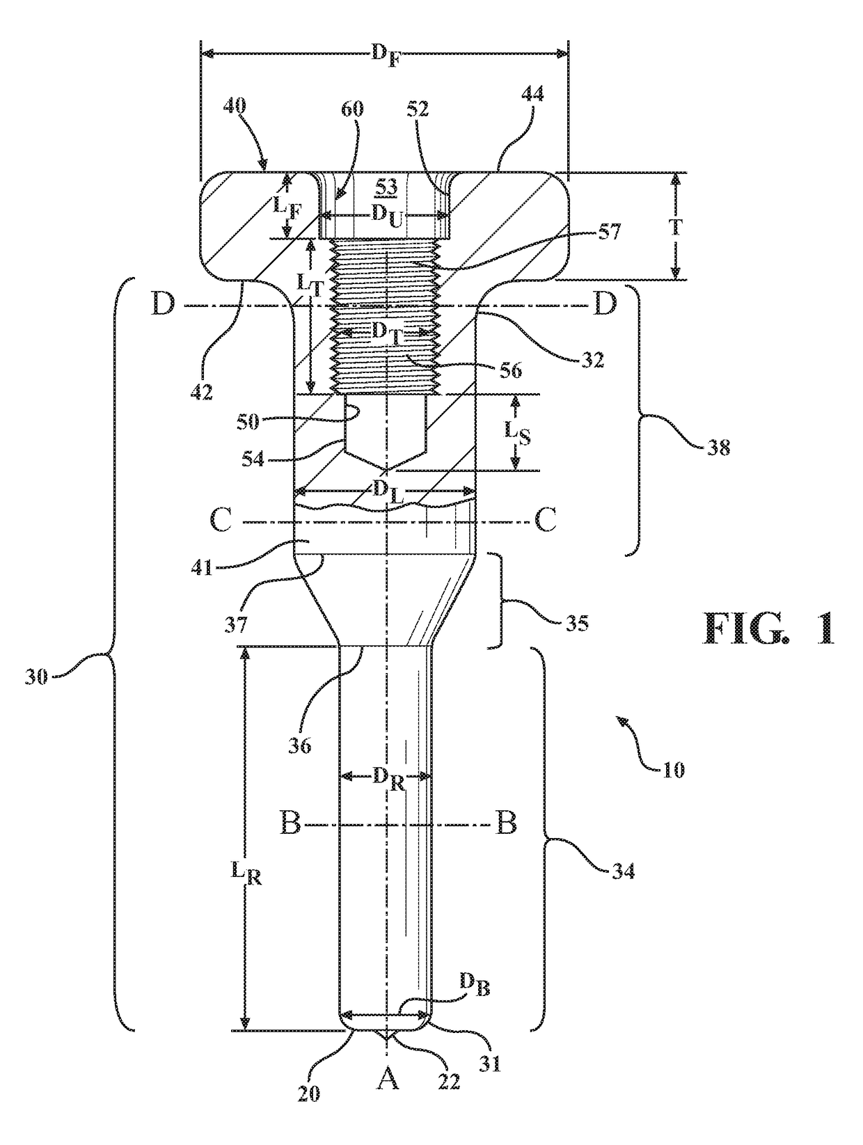
[0020]Referring to the figures, wherein like numerals indicate corresponding parts throughout the several views, a stand-off weld stud 10 is generally shown. As best illustrated in FIGS. 1 and 2, the weld stud 10 generally includes a shank 30 that extends along a center axis A between a first shank end 31 and a second shank end 32. The weld stud 10 is preferably a solitary body that may be formed from any structural material suitable for welding using a weld stud welding process, such as carbon steel, stainless steel, or an aluminum alloy. Of course, numerous known material substitutes may be used, as will be understood by those of ordinary skill in the art without departing from the scope of the subject disclosure.

[0021]The shank 30 has a reduced diameter portion 34 that extends axially from the first shank end 31, and a larger diameter portion 38 that extends axially from the second shank end 32 toward the reduced diameter portion 34. The larger diameter portion 38 has a larger di...


PUM


Abstract

A weld stud including a shank that has a reduced diameter portion, and a larger diameter portion. A weld base is defined on the reduced diameter portion and a flange is positioned on the larger diameter portion. A bore wall extends axially through a face of the flange and into the larger diameter portion. The bore wall has a threaded portion that has a threaded diameter for receiving a fastener. A base diameter of the weld base is smaller than a larger diameter of the larger diameter portion and substantially equal to, or smaller than the threaded diameter. The threaded portion is axially spaced from the face of the flange by a first unthreaded portion, which defines a first unthreaded diameter that is larger than the threaded diameter. These features limit the loads transmitted to the fastener, thus allowing the weld stud to withstand shock loads to prevent fastener failures.

Description

CROSS REFERENCE TO RELATED APPLICATIONS[0001]The present application claims priority to U.S. Provisional Patent Application Ser. No. 62 / 217,802, filed on Sep. 12, 2015, the disclosure of which is hereby incorporated by reference in its entirety as though set forth fully herein.BACKGROUND OF THE INVENTION[0002]1. Field of the Invention[0003]This invention relates to weld stud fasteners. More specifically, this invention relates to stand-off weld studs configured to enable attachment of components or assemblies to metal structures, such as the interior of a ship.[0004]2. Description of the Prior Art[0005]Weld studs are typically metallic fasteners that are end-welded to a base attachment structure, such as a metal sheet, plate, or beam, using a weld stud welding process. The weld stud welding process allows weld studs to be welded to various metals to eliminate the need for through holes or possibly a requirement for having access to the opposite side of the base material to which the...

Claims


Application Information

Patent Timeline
Patent Type & Authority Applications(United States)
IPC IPC(8): F16B37/06F16B31/06
CPCF16B31/06F16B37/061B23K35/0288F16B37/06
Inventor CHAMPNEY, CLARK
Owner NELSON STUD WELDING
Learn More