
A method of installing an unbonded flexible pipe

Active Publication Date: 2018-10-18
NAT OILWELL VARCO DENMARK
View PDF4 Cites 1 Cited by
  • Summary
  • Abstract
  • Description
  • Claims
  • Application Information

AI Technical Summary

Benefits of technology

The present invention aims to provide a method that can prevent the corrosion of metallic armoring layers in the unbonded flexible pipe. This will make the armoring layers resistant to local failure due to corrosion and reduce the occurrence of localized H2S damage, such as hydrogen induced cracking or sulfide stress cracking. This will help to maintain the functionality of the unbonded flexible pipe during its expected service time.

Problems solved by technology

From the bore of the pipe gasses, such as CO2 and H2S, may permeate through the sheath into the annular volume and cause corrosion of the armoring layers in the annular volume, which are normally made from steel.
Such corrosive gases may diffuse into the annular volume and attack the steel reinforcing layers.
The annular volume may also accidentally be exposed to water, such as from seawater ingress from a damaged outer sheath, or water vapour diffusing from the bore fluids through the inner sheath and condensing in the annular volume, may result in the corrosion of the steel reinforcing layers.
Such corrosion is normally undesired as it may result in a reduction in the fatigue life of the riser.
In addition, an annular volume exposed to water ingress may also prevent gas from being vented from the annulus, leading to a pressure build up which may result in a rupture in the external sheath and further corrosion issues.
Such a method may result in the leakage of the inert fluid from the annular volume into the surrounding environment.
If the inert fluid is not environmentally benign, this method of corrosion mitigation may be associated with a mild degree of environmental damage.
However, if local conditions concentrate the corrosion to a localized zone, even a modest increased corrosion may have significant impact on local pipe properties and lead to damage.

Method used


Image

  • A method of installing an unbonded flexible pipe
  • A method of installing an unbonded flexible pipe
  • A method of installing an unbonded flexible pipe

Examples


Embodiment Construction

[0082]The invention will be explained more fully below in connection with a preferred embodiment and with reference to the drawings in which:

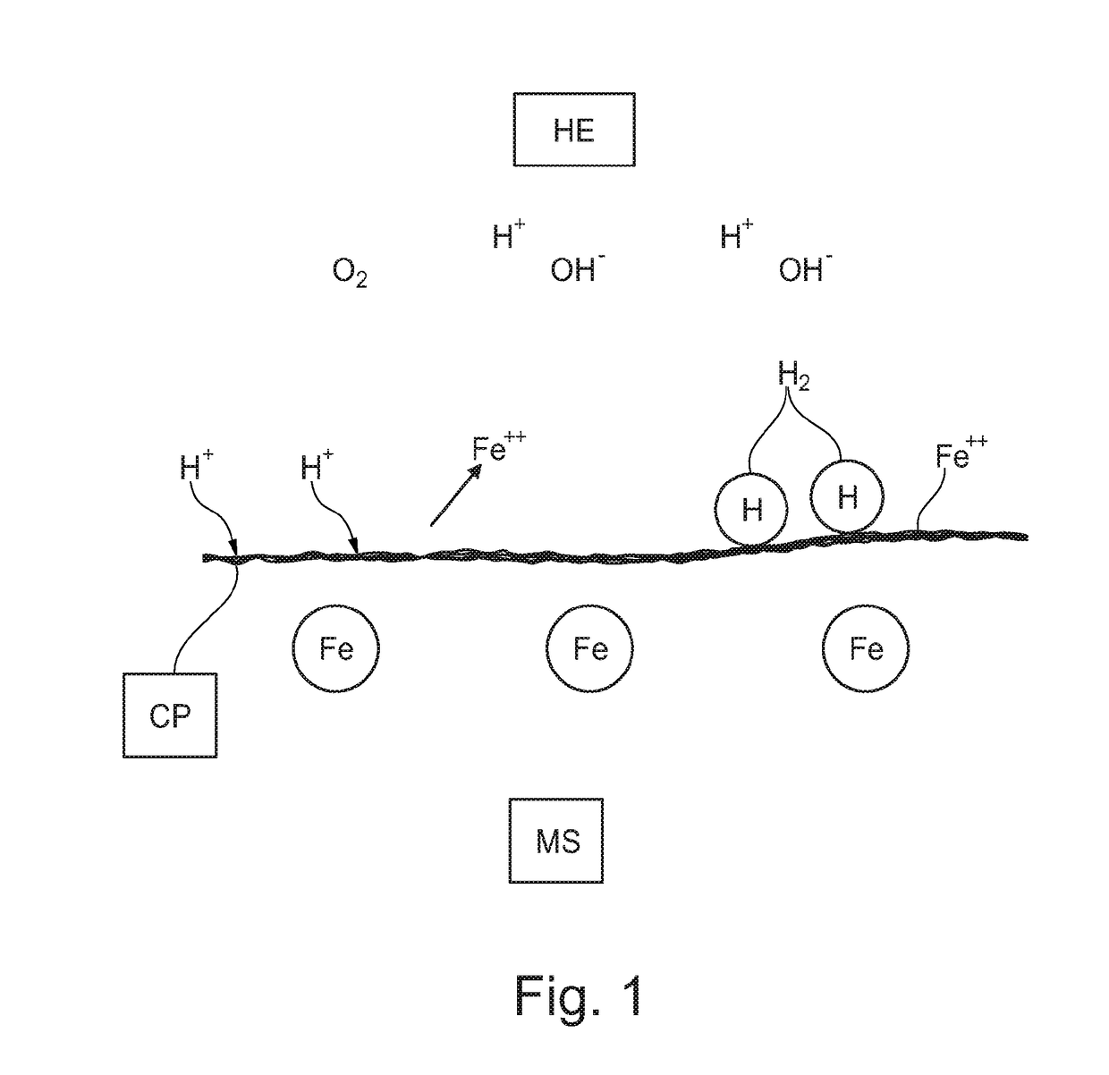
[0083]FIG. 1 shows the principles of corrosion;

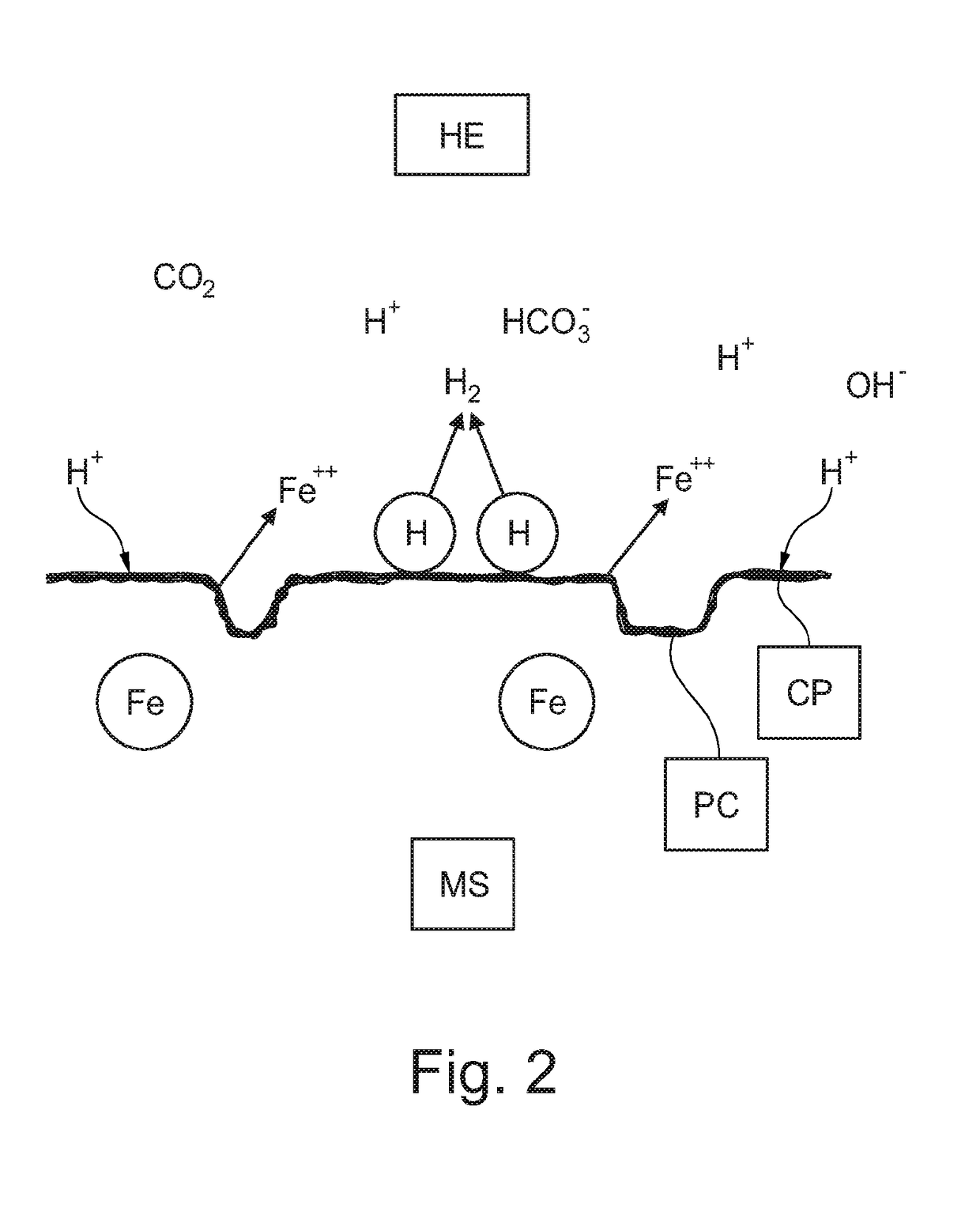
[0084]FIG. 2 shows the principles of “sweet corrosion”;

[0085]FIG. 3 shows the principles of “sour corrosion”;

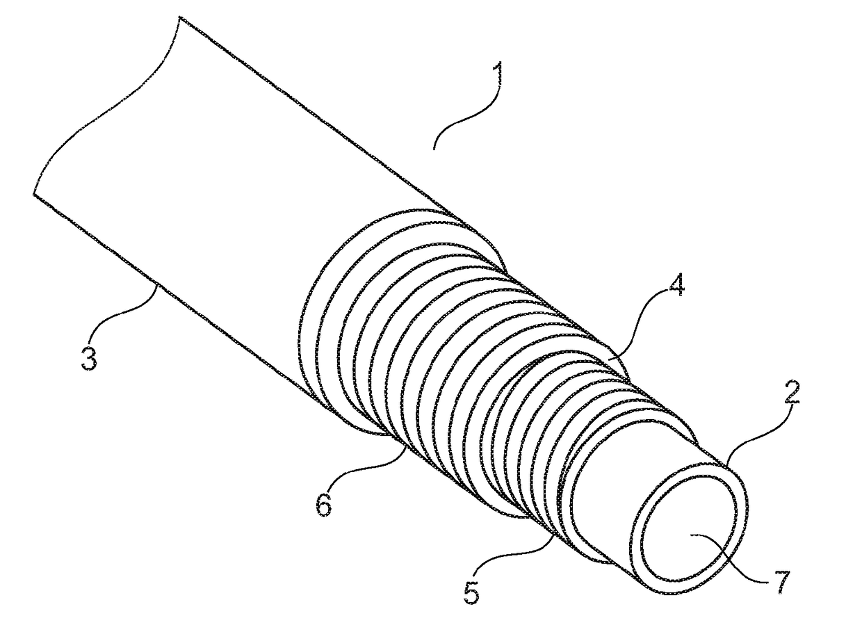
[0086]FIG. 4 shows an embodiment of an unbonded flexible pipe;

[0087]FIG. 5 shows the annulus in an unbonded flexible pipe; and

[0088]FIG. 6 shows an unbonded pipe with wick material.

[0089]The drawings are only schematical and only intended for showing the principles of the present invention. Details which do not form part of the invention have been omitted. The same reference numbers are used for the same parts in the drawings.

[0090]FIG. 1 illustrates the principles of “simple” corrosion at a metallic surface MS in contact with water and oxygen present in the humid environment HE. The surface of the metal is corroded due to the metallic irons reaction with acid (hydrogen ions) and the iron on...


PUM


Abstract

The present invention relates to a method of installing an unbonded flexible pipe with a bore for transportation of fluid wherein the unbonded flexible pipe comprises an outer sheath, an inner sealing sheath inside the outer polymer sheath, an annulus between said outer sheath and said inner sealing sheath and at least one metallic armor layer comprising iron located in said annulus, wherein the method comprises filling at least a part of the annulus with a corrosion promoting liquid before or after installing the unbonded flexible pipe between a first installation and a second installation.

Description

[0001]The present invention relates to a method of installing an unbonded flexible pipe with a bore for transportation of fluid. The invention further relates to a subsea system comprising an unbonded flexible pipe and a first and a second installation wherein at least one of the first and the second installations is a subsea installation.BACKGROUND OF THE INVENTION[0002]Unbonded flexible pipes are frequently used as flexible risers or flexible flowlines for transport of fluid hydrocarbons such as oil and gas. The unbonded flexible pipes convey the fluids from a hydrocarbon reservoir located under the sea bed to a floating structure. The fluid may be a hydrocarbon fluid, such as natural gas or oil, depending upon the nature of the hydrocarbon reservoir, or an injection fluid such as water. The fluids, which are transported to the floating structure, can be processed, for example by compression and / or further treatment.[0003]Flexible unbonded pipes of the present type are for example...

Claims


Application Information

Patent Timeline
IPC IPC(8): E21B19/22F16L1/15F16L58/00F16L11/08E21B17/01
CPCE21B19/22F16L1/15F16L58/00F16L11/081E21B17/01F16L2011/047C23F13/00F16L11/083F16L11/20C23F2213/31C23F2213/22C23F2213/32
Inventor GUDME, JONASRUBIN, ADAMHAAHR, MARIE
Owner NAT OILWELL VARCO DENMARK
Learn More