
Joined material and method of manufacturing same

Active Publication Date: 2015-12-03
TOYO TANSO KK
View PDF4 Cites 0 Cited by
  • Summary
  • Abstract
  • Description
  • Claims
  • Application Information

AI Technical Summary

Benefits of technology

The present invention allows for the easy joining of a metal layer and a carbon material layer, while ensuring a large thickness of the metal layer. Additionally, the joined material is resistant to failure.

Problems solved by technology

However, the carbon materials have problems such as redeposition and wearing due to plasma.
However, tungsten also has problems, such as heavy weight and poor machinability.
Nevertheless, it is generally difficult to join the two materials because tungsten or the like has a high melting point and the two materials have a thermal expansion difference.

Method used


Image

  • Joined material and method of manufacturing same
  • Joined material and method of manufacturing same
  • Joined material and method of manufacturing same

Examples


embodiments

First Embodiment

example 1

[0070]0.25 g of SiC (containing Y2O3 and Al2O3, serving as the sintering aid agent, the proportions of which are respectively 3 mass % and 6 mass % relative to SiC) and 25 g of tungsten powder were disposed in that order on a CFC layer (carbon fiber composite material made of Toyo Tanso Co., Ltd [trade name: CX2002U] having a diameter of 40 mm, a thickness of 10 mm, and an ash content of 5 ppm), to thereby prepare a laminated material. Next, the laminated material was sintered under vacuum for 5 minutes by pulse current sintering using a SPS technique (spark plasma sintering technique) under the conditions of a temperature of 1800° C. and a pressure of 30 MPa, to prepare a joined material.

[0071]The joined material prepared in this manner is hereinafter referred to as a joined material A1.

Example 2

[0072]A joined material was fabricated in the same manner as described in Example 1 above, except that the amount of the tungsten powder was set at 125 g.

[0073]The joined material prepared ...

second embodiment

Example 1

[0088]A joined material was fabricated in the same manner as described in Example 1 of the first embodiment above, except that an isotropic graphite material (IG-12 made by Toyo Tanso Co., Ltd., with an open pore rate of about 16%) having a diameter of 25 mm and a thickness of 4 mm was used in place of the CFC layer, that SiC and the tungsten powder were disposed on both sides of the isotropic graphite material, and that the temperature at the time of sintering was set at 1700° C.

[0089]The joined material prepared in this manner is hereinafter referred to as a joined material B1.

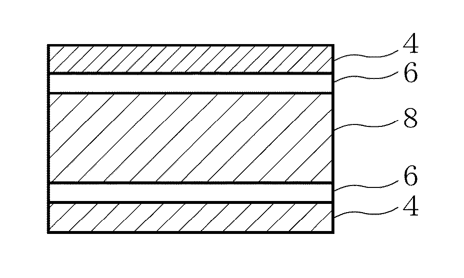
[0090]The outline of the structure of the joined material B1 is as follows. As illustrated in FIG. 5, the intermediate layer 6 containing the elements W, Si, and C is formed on each of the upper and lower surfaces of the isotropic graphite material 8, and the tungsten layer 4 is further formed on each of the outer sides of the mixed layers 6.


PUM

PropertyMeasurementUnit
Lengthaaaaaaaaaa
Fractionaaaaaaaaaa
Thicknessaaaaaaaaaa

Abstract

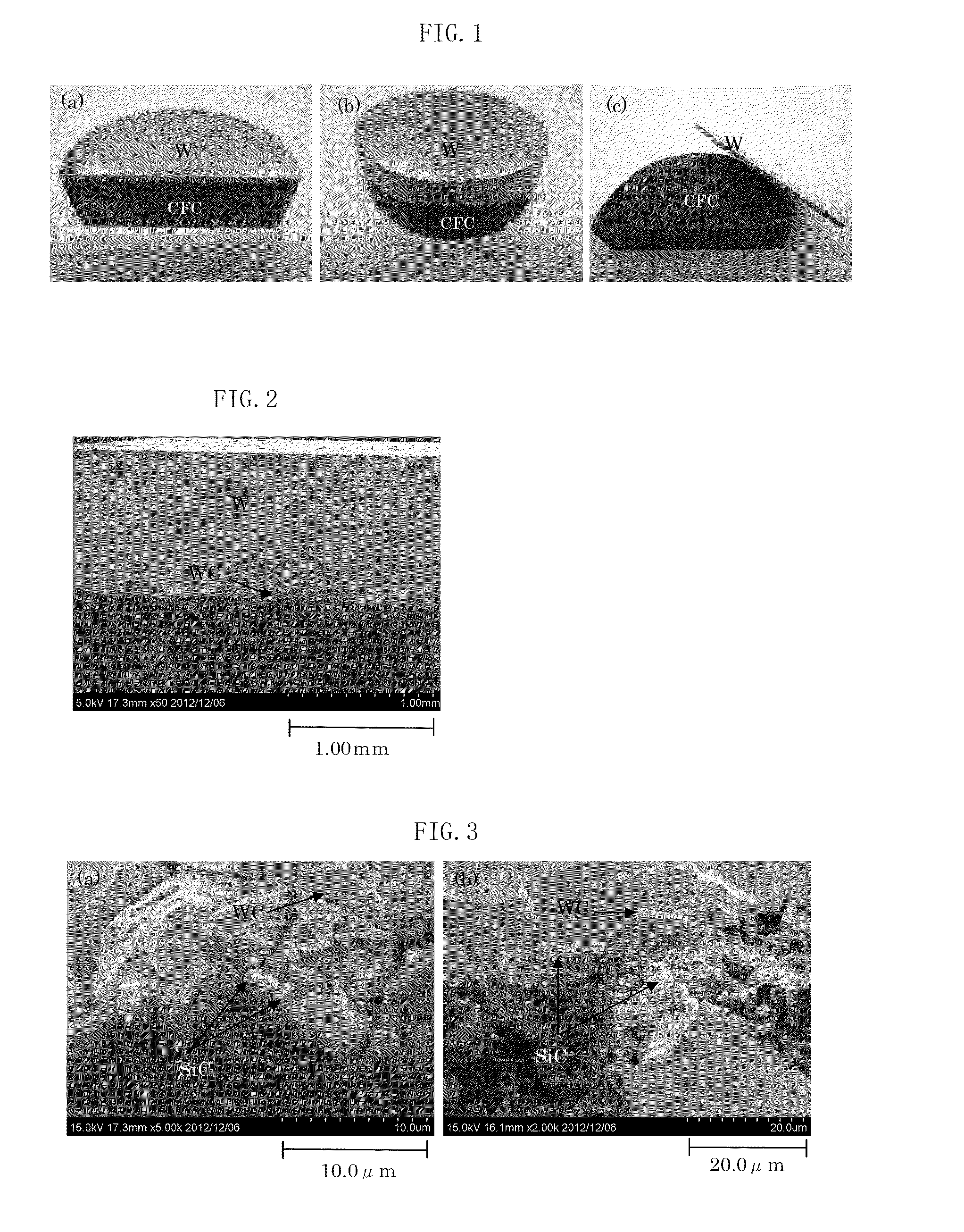
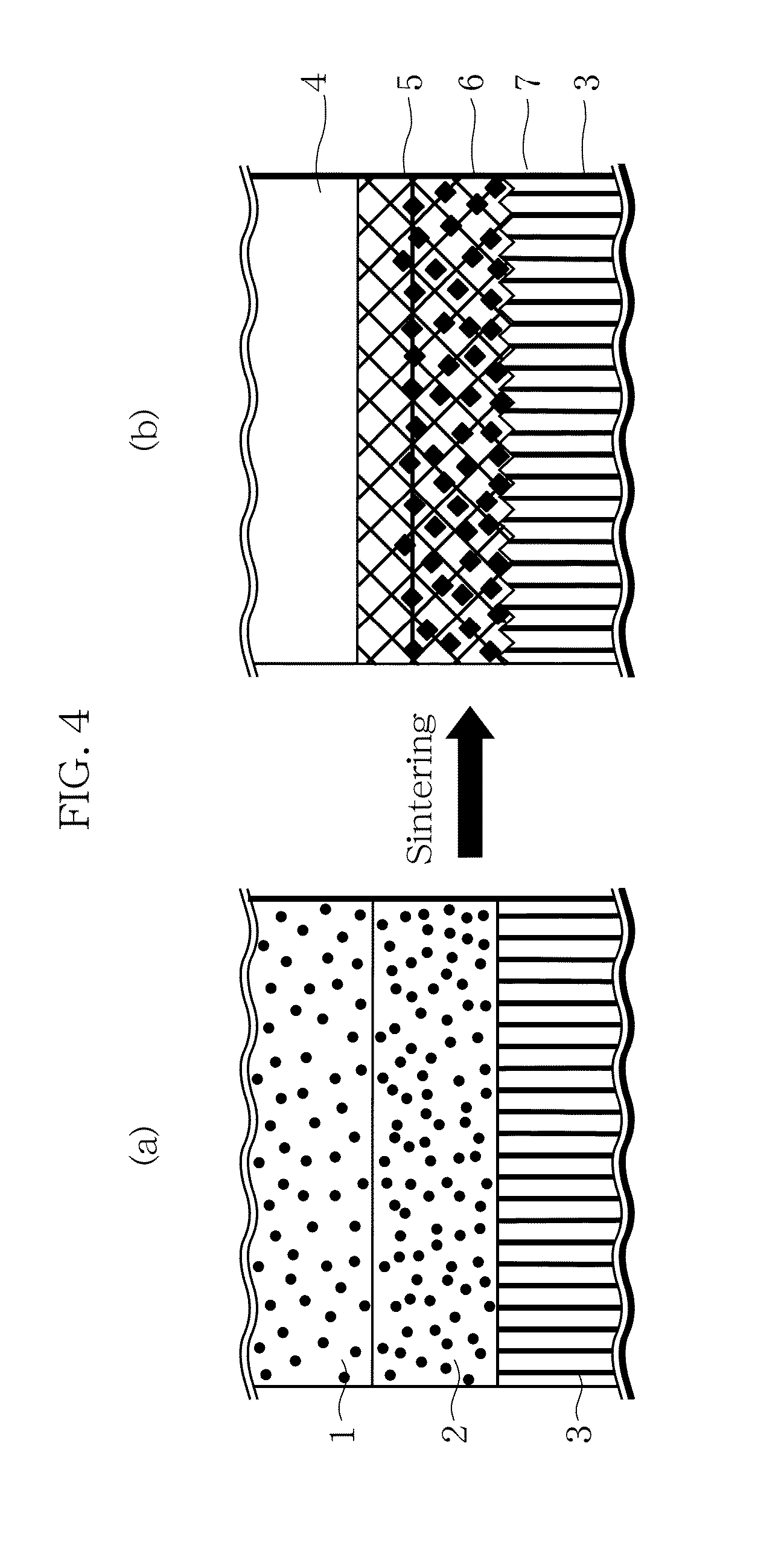
A joined material and a method of manufacturing the joined material are provided which enable a metal layer and a carbon material layer to be easily joined to each other while making the thickness of the metal layer larger and which can inhibit failure.A joined material includes a CFC layer (3) and a tungsten layer (4) that are joined to each other. A sintered tungsten carbide layer (5), a mixed layer (6) of SiC and WC, and SiC and WC (7) that have been sintered while intruding into the CFC layer (3), are formed between the CFC layer (3) and the tungsten layer (4), and these layers (3, 4, 5, 6, and 7) are joined to each other by sintering.

Description

TECHNICAL FIELD[0001]The present invention relates to a joined material and a method of manufacturing the same. More particularly, the invention relates to a joined material of a high-melting point metal and a carbon material, and a method of manufacturing the same.BACKGROUND ART[0002]Carbon materials such as CFC (carbon fiber-reinforced carbon composite material) and graphite material have the advantages that they do not melt even at a high temperature of 3000° C. or higher and that they are less likely to cause the deformation resulting from heat than metals. In view of this fact, it has been proposed to use a joined material in which a cooling pipe (of copper alloy or stainless steel) is joined to CFC or graphite, for a divertor plate of a nuclear fusion apparatus (see Patent Literature 1 listed below). However, the carbon materials have problems such as redeposition and wearing due to plasma. For this reason, the use of tungsten in place of CFC has been investigated. However, tu...

Claims


Application Information

Patent Timeline
IPC IPC(8): C04B37/02B32B9/04B32B37/06B32B9/00
CPCC04B37/025B32B9/007Y10T428/24545B32B37/06B32B2264/107B32B9/041C04B2237/083C04B2237/385C04B2237/404C04B2237/704C04B2237/706C04B2237/708C04B2237/72G21B1/13B32B7/12B32B9/005B32B9/045B32B27/20B32B2262/106C04B2237/363C04B2237/403Y02E30/10
Inventor MIYAMOTO, YOSHINARIFUJITA, ICHIRODOI, MEGUMUMATSUMOTO, TAIHEIOKUNI, TOMOYUKINAKAMURA, FUMISHIGECHEN, WEIWU
Owner TOYO TANSO KK
Learn More