Method and apparatus for simple angle of arrival estimation

a technology of arrival estimation and angle, applied in the direction of direction finders, instruments, measurement devices, etc., can solve the problems of low hardware and computational complexity of sbss, failure of sbs to estimate aoa, and greater hardware and computational complexity

Active Publication Date: 2017-03-16
QATAR UNIVERSITY
View PDF0 Cites 23 Cited by
  • Summary
  • Abstract
  • Description
  • Claims
  • Application Information

AI Technical Summary

Benefits of technology

[0010]The method and apparatus for a simple angle of arrival estimation are used for estimating the angle of arrival of a received signal by a switched beam antenna array. The switched beam antenna array first collects an omnidirectional signal to be used as a reference signal. A main beam thereof is then switched to scan an angular region of interest. The collected signals from the switched beams are cross-correlated with the reference signal to determine the angle of arrival of the received signal. The cross-correlation coefficient is the highest at the true angle of arrival and relatively negligible otherwise.
[0011]For the example of a uniform linear array with uniform excitation, the method for simple angle of arrival estimation includes the following steps: (a) receiving an om

Problems solved by technology

The AoA estimation techniques that use AAS can operate at lower signal-to-noise ratios (SNRs) than the conventional switched beam system (SBS) technique, but has greater hardware and computational complexities.
In other words, the hardware and computational complexities of SBSs are low.
However, if the power of the received signal is lower than the receiver sensitivity; i.e., at low signal to

Method used


Image

  • Method and apparatus for simple angle of arrival estimation
  • Method and apparatus for simple angle of arrival estimation
  • Method and apparatus for simple angle of arrival estimation

Examples


Embodiment Construction

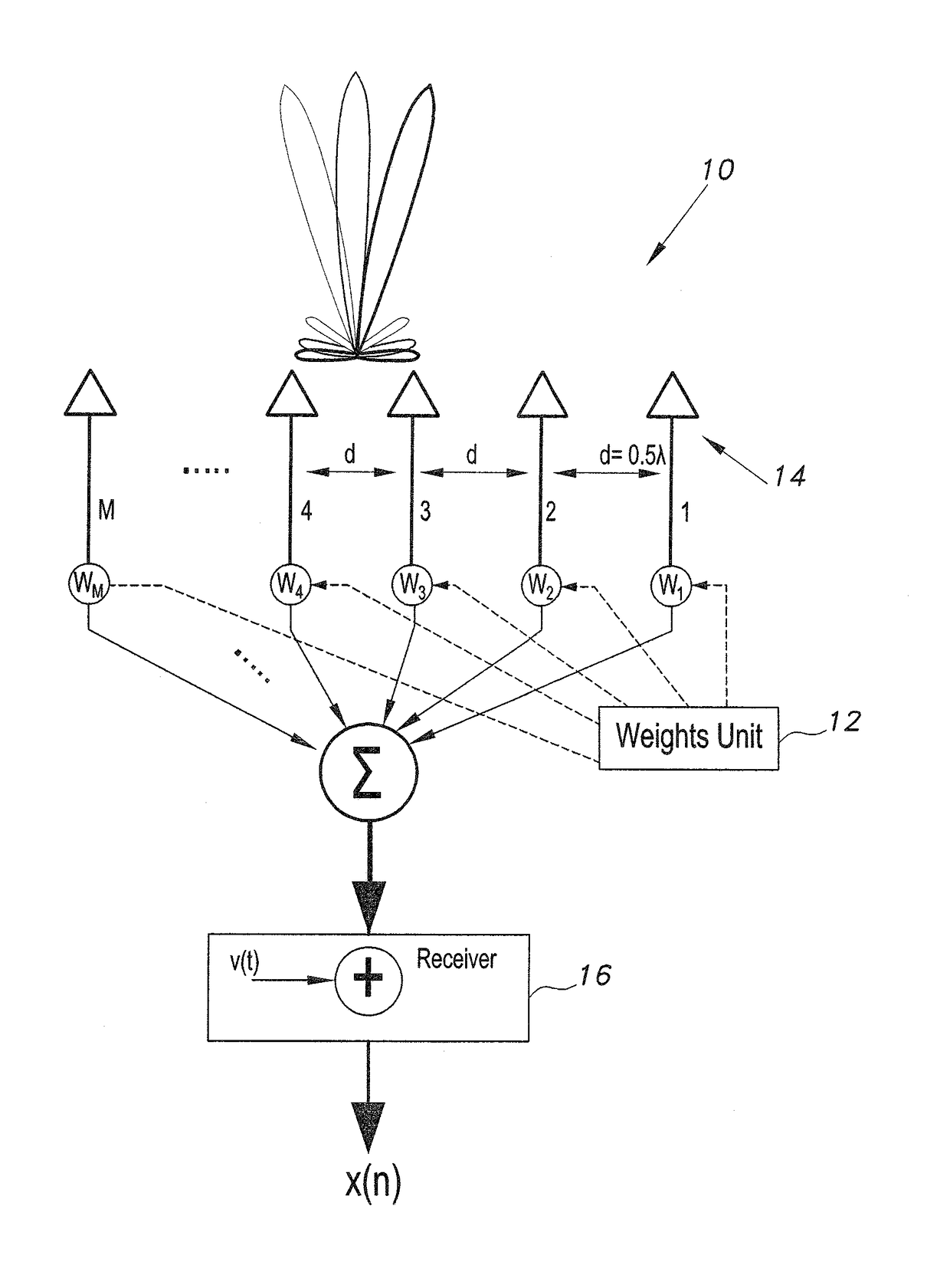
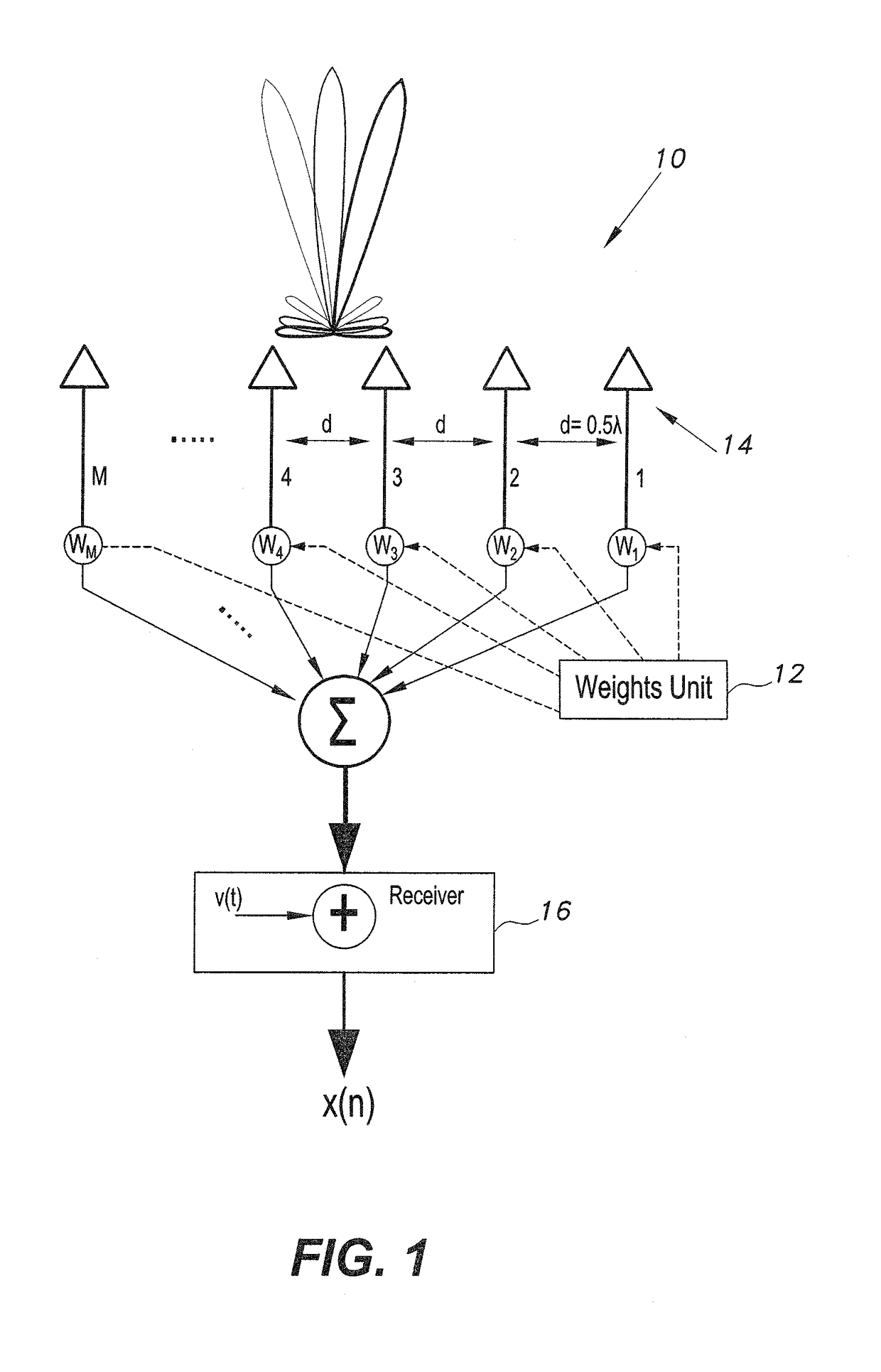
[0031]A method and apparatus for simple angle of arrival estimation are used for estimating the angle of arrival of a received signal by a switched beam antenna array. The switched beam antenna array first collects an omnidirectional signal to be used as a reference signal. A main beam thereof is then switched to scan an angular region of interest. The collected signals from the switched beams are cross-correlated with the reference signal. The cross-correlation coefficient is the highest at the true angle of arrival and relatively negligible otherwise. The collected signal from each beam angle is cross-correlated with the omnidirectional reference signal to determine the angle of arrival of the received signal.

[0032]Referring now to FIG. 1, a source transmits signal s(t) and the receiver is equipped with a switched beam system (SBS) which includes M antenna elements, which are separated by a fixed separation d and operate at frequency f. The antenna array has an array response vect...


PUM


Abstract

The method and apparatus for angle of arrival estimation are used for estimating the angle of arrival of a received signal by a switched beam antenna array and a single receiver. The switched beam antenna array first collects an omnidirectional signal to be used as a reference signal. A main beam thereof is then switched to scan an angular region of interest. The collected signals from the switched beams are cross-correlated with the reference signal. The cross-correlation coefficient is the highest at the true angle of arrival and relatively negligible otherwise. The collected signal from each beam angle is cross-correlated with the omnidirectional reference signal to determine the angle of arrival of the received signal.

Description

CROSS-REFERENCE TO RELATED APPLICATION[0001]This application claims the benefit of U.S. Provisional Patent Application Ser. No. 62 / 219,617, filed on Sep. 16, 2015.BACKGROUND OF THE INVENTION[0002]1. Field of the Invention[0003]The present invention relates to angle of arrival estimation for signals, and particularly to a system and method utilizing cross correlation for estimating the angle of arrival of a received signal by a switched beam antenna array.[0004]2. Description of the Related Art[0005]An adaptive array system (AAS) can steer a beam in any desired direction by setting the weights across the antenna array elements. AAS requires M receivers to estimate the angle of arrival (AoA), where M is the number of antenna elements in the array. The AoA estimation techniques that use AAS can operate at lower signal-to-noise ratios (SNRs) than the conventional switched beam system (SBS) technique, but has greater hardware and computational complexities.[0006]The switched beam system ...

Claims


Application Information

Patent Timeline
IPC IPC(8): G01S3/38G01S3/06
CPCG01S3/065G01S3/38
Inventor BADAWY, AHMEDKHATTAB, TAMERTRINCHERO, DANIELEELFOULY, TAREKMOHAMED, AMR
Owner QATAR UNIVERSITY
Why Eureka
Try Eureka