
Generating probabilistic estimates of rainfall rates from radar reflectivity measurements

a radar reflectivity and probability estimation technology, applied in the field of computer systems, can solve the problems of large rainfall quantities, affecting the yield potential of crops, and inferred precipitation amounts that do not contain the same level of accuracy as gauge measurements

Active Publication Date: 2017-03-16
THE CLIMATE CORP
View PDF0 Cites 29 Cited by
  • Summary
  • Abstract
  • Description
  • Claims
  • Application Information

AI Technical Summary

Benefits of technology

The claims section of the patent text is a summary of the disclosure. The technical effect of this patent is to provide a substantial improvement in the technology used to detect and measure the concentration of a specific substance in a sample. This improvement can lead to more accurate and reliable results, which can be useful in various fields such as medical diagnosis or environmental monitoring.

Problems solved by technology

For farmers, rainfall is a large factor in determining how much water a crop receives, thereby altering the potential yield for the crop.
While rainfall has many positive effects, such as giving life to crops, large quantities of rainfall can also have severe repercussions, such as by causing floods or resulting in standing or ponding water that can inundate seedlings or mature crops.
Precipitation amounts in non-gauge locations may be inferred from the measurements at surrounding gauge locations, but the inferred precipitation amounts do not contain the same levels of accuracy as the gauge measurements.
A drawback with using radar reflectivity to measure the rainfall rate is that the radar reflectivity at best creates an estimate of the actual rainfall.
The persistent problem is that the actual error in the rainfall rates is not measured or computed.
If these variances are not understood and presented to a farmer, the farmer may not be able to make informed decisions with respect to the crop.

Method used


Image

  • Generating probabilistic estimates of rainfall rates from radar reflectivity measurements
  • Generating probabilistic estimates of rainfall rates from radar reflectivity measurements
  • Generating probabilistic estimates of rainfall rates from radar reflectivity measurements

Examples


Embodiment Construction

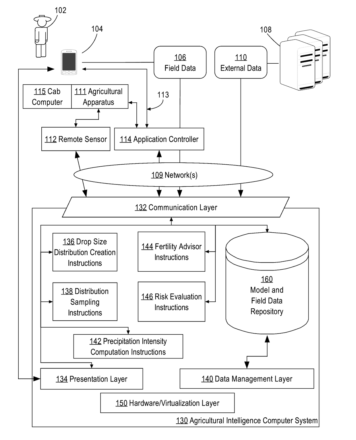
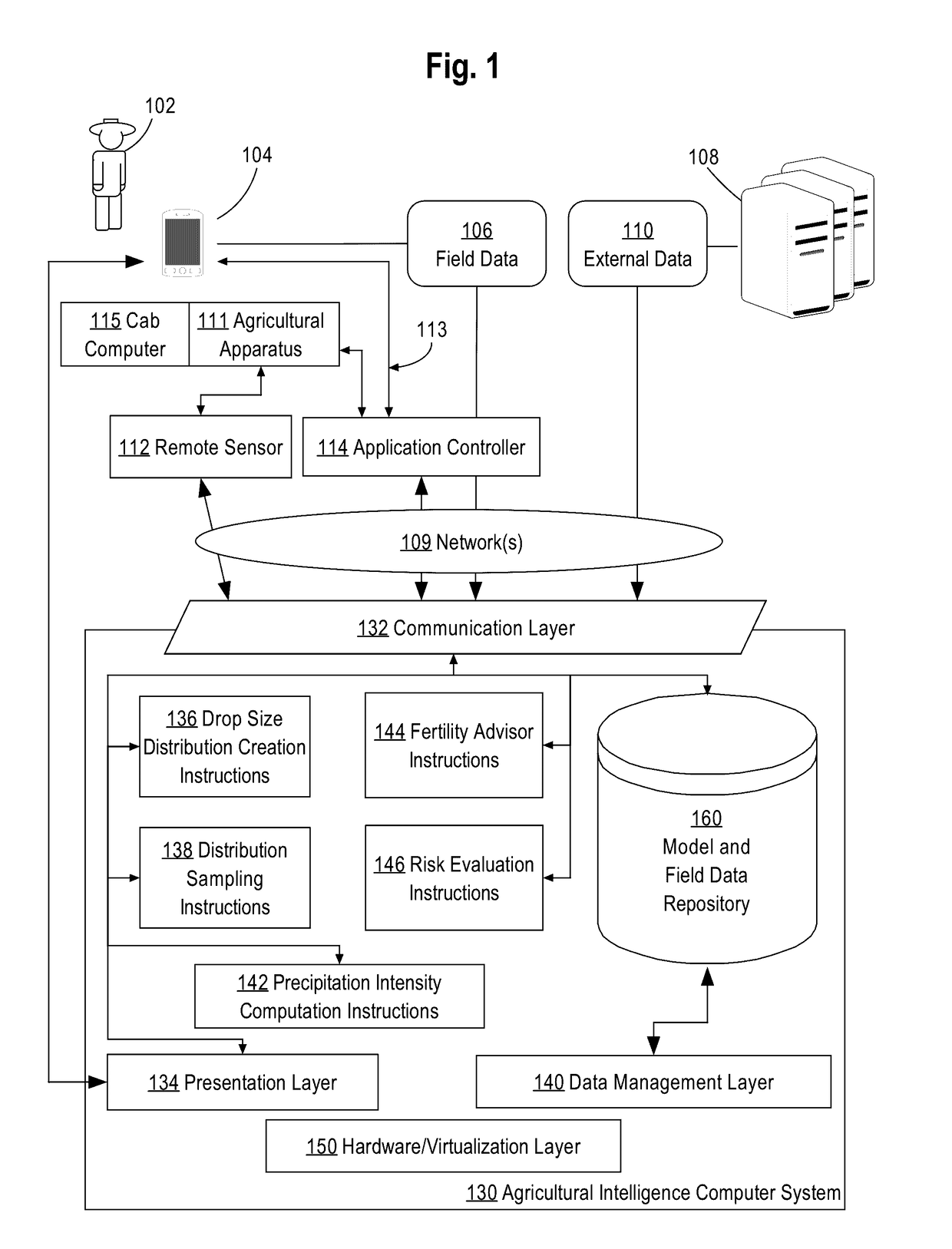
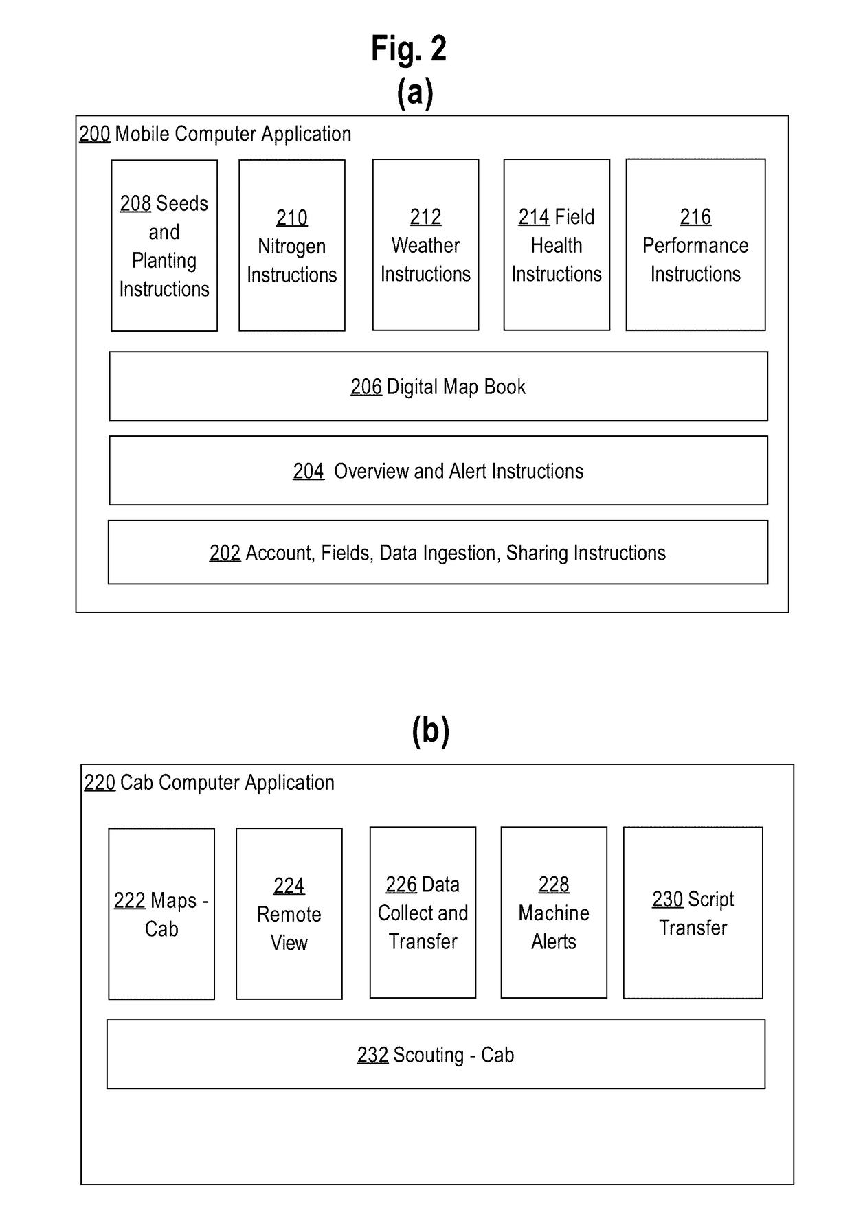
[0021]In the following description, for the purposes of explanation, numerous specific details are set forth in order to provide a thorough understanding of the present disclosure. It will be apparent, however, that embodiments may be practiced without these specific details. In other instances, well-known structures and devices are shown in block diagram form in order to avoid unnecessarily obscuring the present disclosure. The description is provided according to the following outline:[0022]1. GENERAL OVERVIEW[0023]2. EXAMPLE AGRICULTURAL INTELLIGENCE COMPUTER SYSTEM[0024]2.1. STRUCTURAL OVERVIEW[0025]2.2. APPLICATION PROGRAM OVERVIEW[0026]2.3. DATA INGEST TO THE COMPUTER SYSTEM[0027]2.4. PROCESS OVERVIEW-AGRONOMIC MODEL TRAINING[0028]2.5. IMPLEMENTATION EXAMPLE-HARDWARE OVERVIEW[0029]3. ERROR ESTIMATION[0030]3.1. RECEIVING RADAR DATA[0031]3.2. CREATING A DROP SIZE DISTRIBUTION[0032]3.3. PROBABILISTIC DISTRIBUTION OF RAINFALL INTENSITIES[0033]3.4. SPATIAL MODELING[0034]3.5. SPATIO...


PUM


Abstract

A method and system for generating probabilistic estimates of precipitation intensity from radar reflectivity measurements is provided. In an embodiment, an agricultural intelligence computer system receives radar reflectivity measurements for a particular location from an external data source. The agricultural intelligence computer system constructs a probability distribution of drop sizes describing the probability that the precipitation included drops of various sizes based on the radar reflectivity measurements. The agricultural intelligence computer system samples a plurality of values from the probability of distribution of drop sizes and uses the plurality of values and the radar reflectivity measurements to compute a plurality of rainfall rates. Based on the plurality of rainfall rates, the agricultural intelligence computer system constructs a probability distribution of rainfall rates for the particular location.

Description

BENEFIT CLAIM[0001]This application claims the benefit of provisional application 62 / 216,426, filed Sep. 9, 2015, the entire contents of which is hereby incorporated by reference as if fully set forth herein, under 35 U.S.C. §119(e).COPYRIGHT NOTICE[0002]A portion of the disclosure of this patent document contains material which is subject to copyright protection. The copyright owner has no objection to the facsimile reproduction by anyone of the patent document or the patent disclosure, as it appears in the Patent and Trademark Office patent file or records, but otherwise reserves all copyright or rights whatsoever. © 2015 The Climate Corporation.FIELD OF THE DISCLOSURE[0003]The present disclosure generally relates to computer systems useful in climatology and agriculture. The disclosure relates more specifically to computer systems that are programmed or configured to generate probabilistic estimates of precipitation using radar reflectivity data received from radar devices.BACKGR...

Claims


Application Information

Patent Timeline
Patent Type & Authority Applications(United States)
IPC IPC(8): G01W1/10G06N7/00G06Q50/02G01W1/14
CPCG01W1/10G06Q50/02G06N7/005G01W1/14G01S13/95Y02A90/10G06N7/01
Inventor KLEEMAN, ALEXANDERLAKSHMANAN, VALLIAPPAREID, BETH
Owner THE CLIMATE CORP
Learn More