Video signal transmission system

a video signal and transmission system technology, applied in the field of video signal transmission system, can solve the problems of large-scale physical infrastructure, inability to achieve proper distribution, and impracticality, and achieve the effect of reducing the number of transmission lines

Active Publication Date: 2017-03-16
MEDIA GLOBAL LINKSKK
View PDF7 Cites 11 Cited by
  • Summary
  • Abstract
  • Description
  • Claims
  • Application Information

AI Technical Summary

Benefits of technology

[0016]According to the video signal transmission system of the present invention, by performing efficient load distribution of a video signal, the system can perform large-volume video transmission without requiring a large-scale physical infrastructure such as in the link aggregation.

Problems solved by technology

However, the link aggregation has the following problems.
As a consequence, the link aggregation causes a problem of being unable to achieve proper distribution when transmitting large-volume packets.
Such a requirement involves a large-scale physical infrastructure and is therefore impractical.
Furthermore, in the link aggregation, if one of transmission paths fails in use, the transmission continues by using the remaining transmission paths (automatic fallback).

Method used


Image

  • Video signal transmission system
  • Video signal transmission system
  • Video signal transmission system

Examples


first embodiment

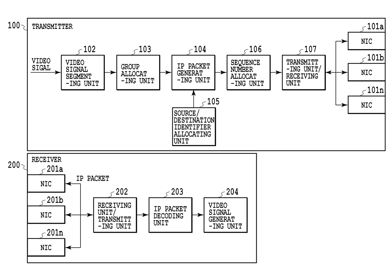
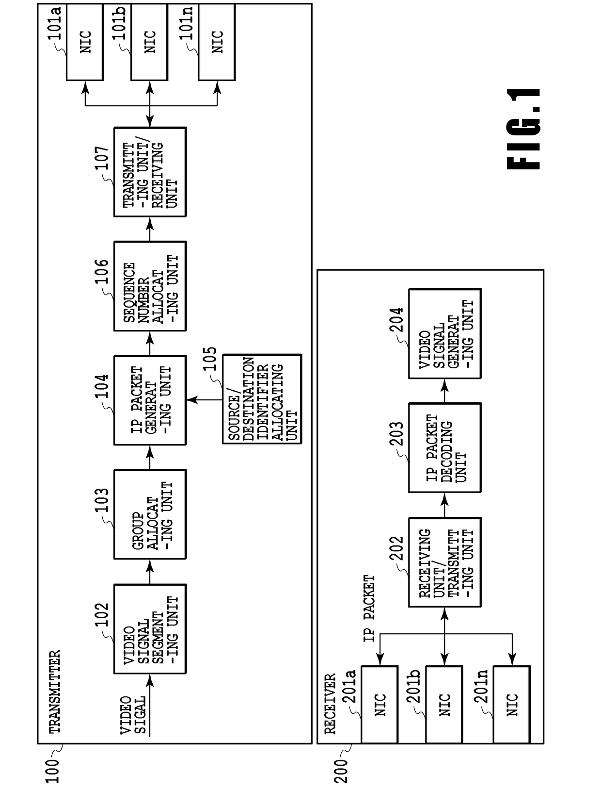
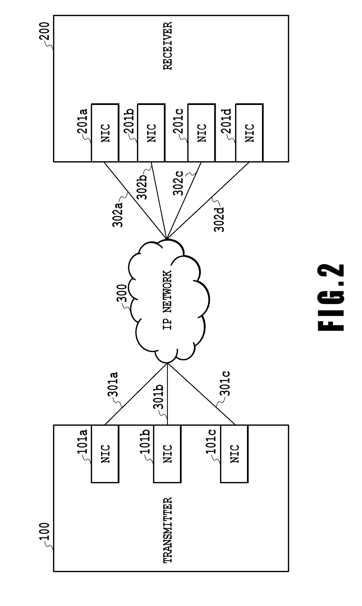
[0043]Next, an example of a video signal transmission system according to a first embodiment of the present invention will be described. FIG. 2 shows an example of transmission paths of the video signal transmission system according to the first embodiment of the present invention. As shown in FIG. 2, the transmitter 100 and the receiver 200 are connected to each other through the IP network 300. Transmission side paths 301a, 301b, and 301c are provided between the transmitter 100 and the IP network 300 (the network device), and are connected to the NICs 101a to 101c, respectively. The transmission side paths 301a to 301c have transmission rates that are equal among them.

[0044]Reception side paths 302a, 302b, 302c, and 302d are provided between the receiver 200 and the IP network 300, and are connected to the NICs 201a to 201d, respectively. The reception side paths 302a to 302d have transmission rates that are equal among them.

[0045]While this embodiment adopts the three-to-four pa...

second embodiment

[0068]Next, an example of a video signal transmission system according to a second embodiment of the present invention will be described with reference to FIG. 5. The second embodiment also employs the configuration of the transmission paths described in FIG. 2. FIG. 5 is a diagram showing an example of processing steps to be performed on the transmitter side of the video signal transmission system according to the second embodiment of the present invention.

[0069]First, the video signal segmenting unit 102 segments the video signal VS into the twelve fixed-length pieces of data D1 to D12 as with the first embodiment.

[0070]Next, the sequence number allocating unit 106 allocates sequence numbers 1 to 12, which are sequentially defined in chronological order, to the respective pieces of data D1 to D12 segmented by the video signal segmenting unit 102. While the two types of the sequence numbers are allocated in the first embodiment, the sequence numbers of the single type are allocated...

third embodiment

[0075]Next, an example of a video signal transmission system according to a third embodiment of the present invention will be described. FIG. 7 shows an example of transmission paths of the video signal transmission system according to the third embodiment of the present invention. As shown in FIG. 7, the transmitter 100 and the receiver 200 are connected to each other through the IP network 300. The transmission side paths 301a, 301b, and 301c are provided between the transmitter 100 and the IP network 300 (the network device), and are connected to the NICs 101a to 101c, respectively. Here, the transmission path configuration of this embodiment is different from that of the first embodiment in that the transmission side paths 301a to 301c have different transmission rates. Specifically, in the transmission path configuration according to the third embodiment, the transmission side path 301a has a transmission rate of 100 Gbps while each of the transmission side paths 301b and 301c ...


PUM


Abstract

The present invention provides a transmitter including a first source network interface connected to a first transmission path of a plurality of transmission paths, an nth source network interface connected to an nth transmission path of the plurality of transmission paths, a video signal segmenting unit configured to segment a video signal into a plurality of pieces of data, a sequence number allocating unit configured to allocate a sequence number to each of the plurality of pieces of data, an IP packet generating unit configured to generate a plurality of IP packets by adding IP headers to the plurality of pieces of data, and a transmitting unit configured to allocate each of the plurality of IP packets to one of the first source network interface to the nth source network interface, respectively, and to transmit the IP packets independently.

Description

CROSS-REFERENCES TO RELATED APPLICATIONS[0001]This application claims the benefit of Japanese Patent Application No. 2015-178774, filed Sep. 10, 2015, which is hereby incorporated by reference wherein in its entirety.BACKGROUND OF THE INVENTION[0002]Field of the Invention[0003]The present invention relates to a video signal transmission system, or more specifically, to a video signal transmission system for distributing video signals through a plurality of transmission paths.[0004]Description of the Related Art[0005]Video signals are transmitted by means of multicast in various cases where a video image shot with a camera installed in a stadium is transmitted to a broadcast station, and where a video image is transmitted from a broadcast station. When such a video signal is transmitted, the video signal is converted into IP packets, which are then transmitted through an IP network. Conventional IP transmission of the video signal has been based on the premise that a plurality of vid...

Claims


Application Information

Patent Timeline
Patent Type & Authority Applications(United States)
IPC IPC(8): H04L29/12H04L29/06H04L45/24H04L47/41H04L47/43
CPCH04L61/2007H04L65/60H04L61/6022H04L12/2863H04L45/24H04L47/125H04L69/14H04L65/762H04L1/188H04L49/201H04L1/1841H04L61/5007H04L2101/622
Inventor NAKAMURA, KAZUNORINARITA, KAZUKI
Owner MEDIA GLOBAL LINKSKK
Why Eureka
Try Eureka