Eureka AIR delivers breakthrough ideas for toughest innovation challenges, trusted by R&D personnel around the world.

Filter System and Filter Element Having a Glass Fiber Filter Medium and a Sintered Body

a filter system and glass fiber filter medium technology, applied in the direction of filter elements, loose filtering materials, separation processes, etc., can solve the problems of contaminating the filtered fluid, hard and brittle glass fibers of such a glass fiber filter medium, and damage to the high-pressure pump or the injector

Inactive Publication Date: 2017-03-23
MANN HUMMEL GMBH
View PDF5 Cites 0 Cited by
  • Summary
  • Abstract
  • Description
  • Claims
  • Application Information

AI Technical Summary

Benefits of technology

The present invention provides a filter system or a filter element that can keep constituents of a glass fiber filter medium without needing an extra layer. This is accomplished through a process called sintering, which involves combining glass fiber with a plastic material or metal to create a solid structure that prevents damage to downstream components. The sintered body has a specific pore size to minimize flow resistance and allow for proper filtration. The thickness of the sintered body is preferably at least three times the average diameter of sintering beads, which ensures effective blockage of any detached constituents of the filter medium. The invention has a simple manufacturing process and low production costs.

Problems solved by technology

It is known that the glass fibers of such a glass fiber filter medium are hard and brittle.
Upon installation of the glass fiber filter medium in a filter element or in operation of the filter system or of the filter element, glass fiber constituents can therefore become detached from the glass fiber filter medium and can contaminate the filtered fluid.
In particular in case of high pressure injection of a fluid in the form of a fuel into a combustion chamber of a motor vehicle engine, such glass fiber parts or glass fiber fragments can cause damage of a high-pressure pump or of the injector.
An additional filter medium of such a construction increases however the flow resistance of the filter system or of the filter element in a disadvantageous way.
Finally, errors in the processing of the additional filter medium, in particular during embossment and folding, may cause failure of the blocking function of the additional filter medium.

Method used


Image

  • Filter System and Filter Element Having a Glass Fiber Filter Medium and a Sintered Body
  • Filter System and Filter Element Having a Glass Fiber Filter Medium and a Sintered Body

Examples


Embodiment Construction

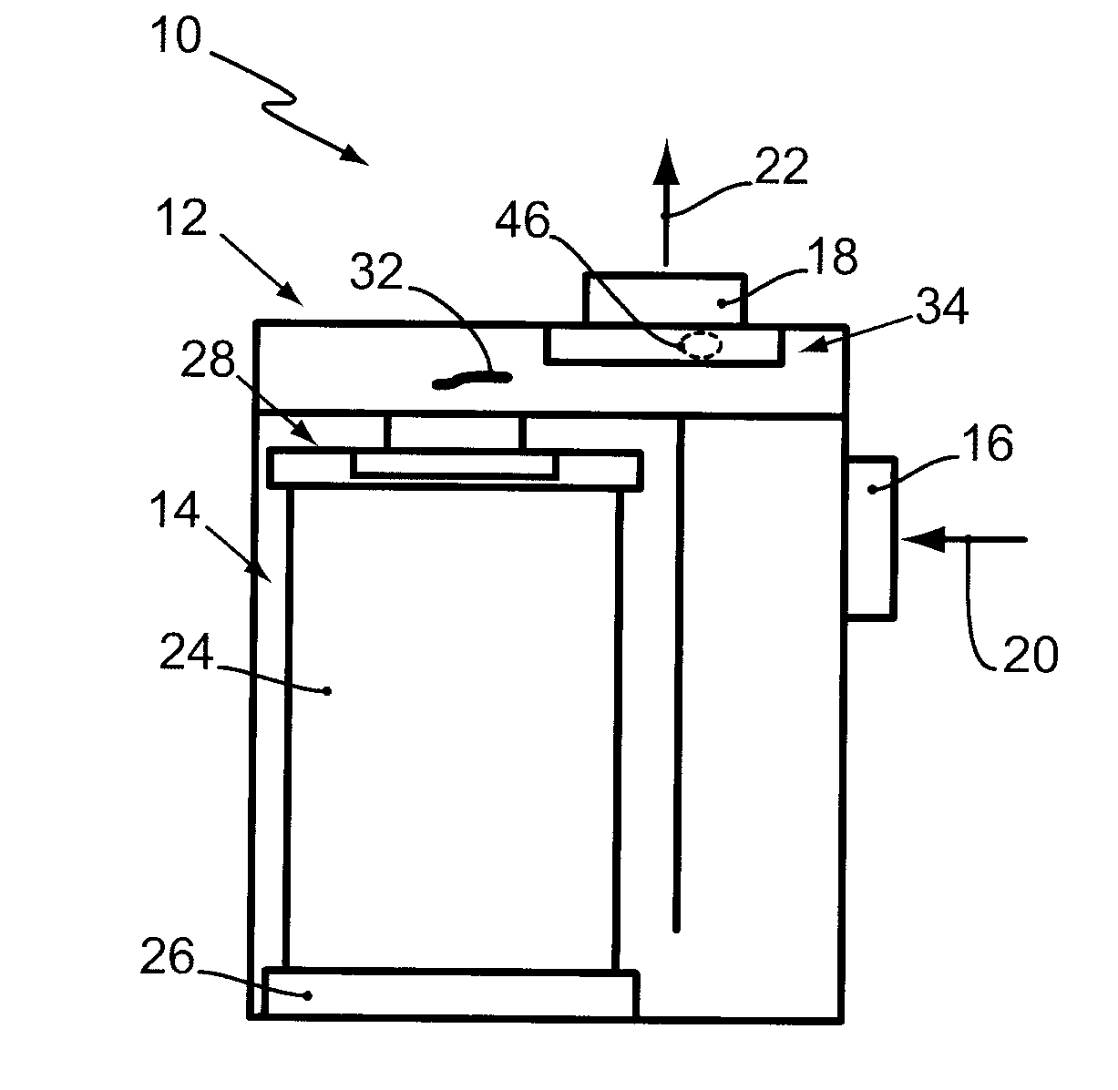
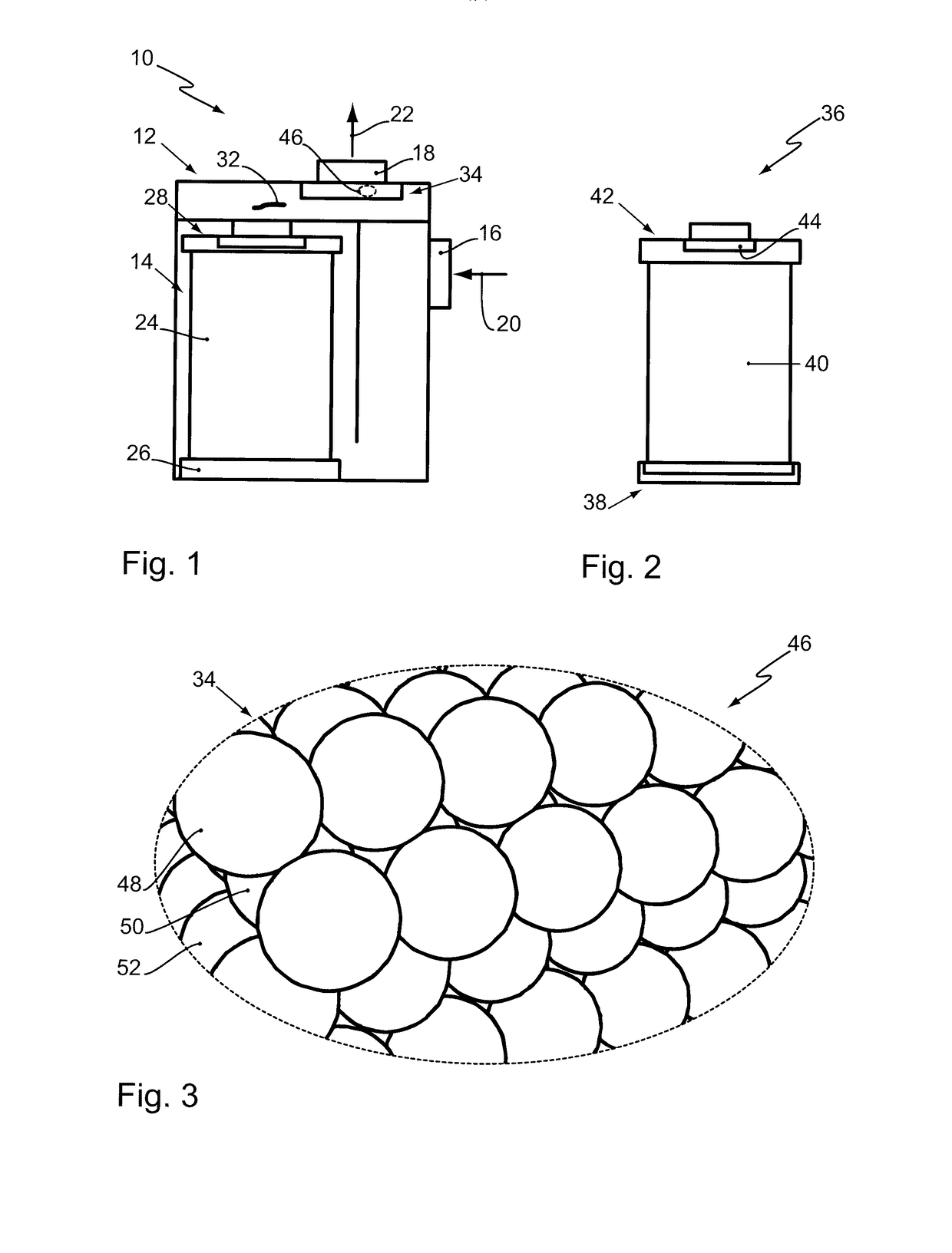
[0032]FIG. 1 shows a filter system 10 according to the invention. The filter system 10 comprises a filter housing 12. In the filter housing 12, an exchangeable first filter element 14 is arranged.

[0033]The filter housing 12 comprises an inlet 16 and an outlet 18 for a fluid to be filtered, in particular for fuel. The filter housing 12 can thus be flowed through, as indicated by arrows 20, 22, wherein the filtering action is substantially realized in the first filter element 14.

[0034]The first filter element 14 comprises a filter medium 24. The filter medium 24 is arranged between a first end plate 26 and a second end plate 28 of the filter element 14 and is designed as a glass fiber filter medium 24. Individual glass fibers can break out of the glass fiber filter medium 24 and can contaminate the fluid. The constituent 32 of the glass fiber filter medium 24 is illustrated particularly large in FIG. 1 for illustration purposes. Realistic constituents 32 of the glass fiber filter medi...


PUM

PropertyMeasurementUnit
Pore sizeaaaaaaaaaa
Thicknessaaaaaaaaaa
Diameteraaaaaaaaaa

Abstract

A filter system for filtering a fluid is provided with a filter housing and a filter element arranged in the filter housing. The filter element has a glass fiber filter medium. A sintered body is arranged fluidically downstream of the glass fiber filter medium for retaining constituents of the glass fiber filter medium entrained in a fluid to be filtered. A pore size of the sintered body is greater than a cross-section of the constituents of the glass fiber filter medium.

Description

CROSS-REFERENCE TO RELATED APPLICATIONS[0001]This application is a continuation application of international application No. PCT / EP2015 / 062063 having an international filing date of 1 Jun. 2015 and designating the United States, the international application claiming a priority date of 2 Jun. 2014, based on prior filed German patent application No. 10 2014 007 813.2, the entire contents of the aforesaid international application and the aforesaid German patent application being incorporated herein by reference.BACKGROUND OF THE INVENTION[0002]The invention concerns a filter system and a filter element for filtering a fluid. The filter system and the filter element are preferably usable in motor vehicles, in particular for filtering fuel.[0003]U.S. Pat. No. 6,096,212 discloses a filter element for liquids and gases. The filter element comprises a filter medium that is arranged between two end disks of the filter element and that is folded, as is known in the art, in a star shape. The...

Claims


Application Information

Patent Timeline
IPC IPC(8): B01D39/20B01D39/16
CPCB01D39/2017B01D39/2034B01D2239/1216B01D2239/065B01D2239/1291B01D39/1661B01D24/10
Inventor SPELTER, LARS
Owner MANN HUMMEL GMBH
Why Eureka
Eureka Blog
Learn More