Coupling system for use with a spindle apparatus of a machine tool

a technology of coupling system and machine tool, which is applied in the direction of programming control, instruments, manufacturing tools, etc., to achieve the effects of favorable synergetic effect, space saving and cost-effective, and cost-effectiveness

Active Publication Date: 2017-03-23
SAUER GMBH
View PDF8 Cites 2 Cited by
  • Summary
  • Abstract
  • Description
  • Claims
  • Application Information

AI Technical Summary

Benefits of technology

[0031]In summary, a versatile, space-saving and cost-effective tool interface system and / or coupling interface system for machine tools is provided which can be used in a particularly space-saving and cost-effective way with favorably synergetic effects with respect to the advantageous energy and signal transmission and / or supply and to advantageously efficient, time-saving and versatile tool change possibilities and accurate tool and processing head alignment, in particular when used for hybrid machine tools where optionally in addition to a conventional machining operation further processing possibilities can be combined, such as tool interface units which have electrical loads and which are used e.g., in the ultrasonic processing, and / or in connection with material deposition processing heads serving to deposit material on the machine tool which conventionally removes material.

Problems solved by technology

Due to the different dimensions of the various processing heads, the problem arises that when a processing head for a machining operation is replaced with a processing head for deposition welding, the device for the energy supply, which is required for the processing head for the machining operation but not for the processing head for deposition welding, stands in the way of the processing head for deposition welding so as to prevent an exchange of the two processing heads.

Method used


Image

  • Coupling system for use with a spindle apparatus of a machine tool
  • Coupling system for use with a spindle apparatus of a machine tool
  • Coupling system for use with a spindle apparatus of a machine tool

Examples


Embodiment Construction

[0048]Examples and embodiments of the present invention are specified below with reference to the enclosed drawings. Equal or similar elements in the drawings can here be designated with equal reference signs, and sometimes also with different reference signs. It is pointed out that the present invention is by no means limited or restricted to the below embodiments and embodiment features thereof but also comprises modifications of the embodiments, in particular those included by modifications of the features of the described examples and / or by combining individual or several features of the described examples on the basis of the scope of the independent claims.

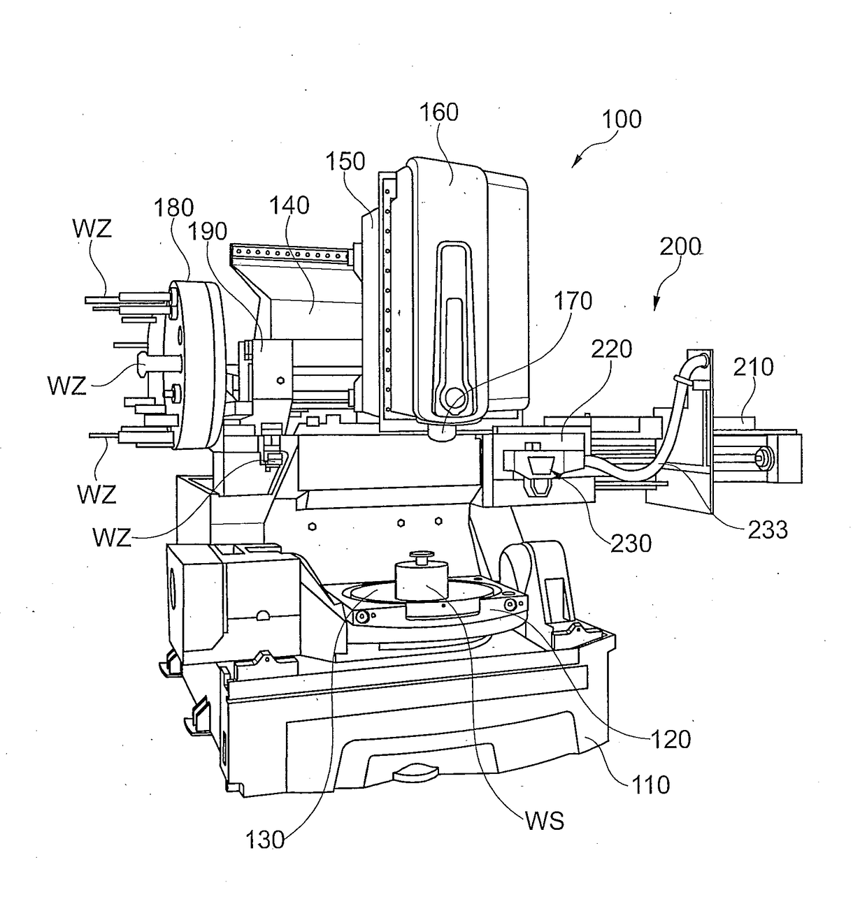
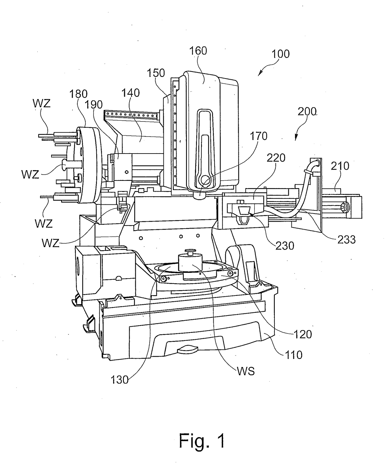
[0049]FIG. 1 shows an exemplary perspective view of a machine tool 100 according to an embodiment of the invention.

[0050]As an example, the machine tool 100 comprises a machine bed 110, on which e.g., a swivel table 120 is arranged which has a rotary table 130, which a rotatably mounted on the swivel table 120 and on which e....


PUM

PropertyMeasurementUnit
electrical energyaaaaaaaaaa
ultrasonic frequencyaaaaaaaaaa
energyaaaaaaaaaa

Abstract

The present invention relates to a coupling system for use at a spindle apparatus of a machine tool, comprising an energy transmission unit with a transmitter coil unit for the contact-free transmission of electrical energy to a receiver coil unit of a tool interface unit with an electrical load and a tool interface portion for accommodation in a tool support of a work spindle of the spindle apparatus, and a coupling interface unit having an interface body element attachable to the spindle apparatus and a second coupling element which is configured to be coupled to a first coupling element of the energy transmission unit by means of a releasable connection.

Description

BACKGROUND[0001]Technical Field[0002]The present application relates to a system and / or coupling system for use with a spindle apparatus of a machine tool.[0003]Description of the Related Art[0004]The prior art discloses machine tools which can be used for both a material-removing processing and a material-depositing processing of a workpiece.[0005]DE 10 2013 224 649 A1 describes a machine tool having a machine control, a machine frame, a workpiece table, a tool support preferably made in accordance with a standard, a plurality of translational and / or rotational axes for adjusting a relative position between workpiece table and tool support, a tool magazine for one or more material-removing, in particular machining, tools, a tool change mechanism for automatically moving tools between tool support and tool magazine, a deposition welding head that can be inserted into the tool support and a storage device for storing des deposition welding head outside the tool support.[0006]WO 2014 / ...

Claims


Application Information

Patent Timeline
Patent Type & Authority Applications(United States)
IPC IPC(8): B23Q1/00H02J50/10
CPCH02J50/10B23Q1/0009B23B31/28B23P23/04B23Q1/70B23Q11/00B23K26/0093B23Q5/043B23Q2220/008B23K26/14B23K26/34B23K26/1462B23Q3/155Y10T483/17B23B37/00B23Q5/54Y10T29/5107Y10T409/309296B23K26/342G05B2219/50245
Inventor SCHWENK, GASTONKETELAER, JENS
Owner SAUER GMBH
Why Eureka
Try Eureka