Optical fibre bend sensor

a technology of optical fibre and bend sensor, which is applied in the direction of optical elements, optical apparatus testing, instruments, etc., can solve the problems of bending of the fibre, weakening the structure being monitored, and strain developing within the fibr

Inactive Publication Date: 2003-09-16
OPTASENSE HLDG LTD
View PDF9 Cites 34 Cited by
  • Summary
  • Abstract
  • Description
  • Claims
  • Application Information

AI Technical Summary

Benefits of technology

This invention provides the advantages of accuracy and relatively non-intrusive bend measurement. Optical fibre assemblies can be produced with very small diameter and embedding within a structure will thus result in minimal disruption of that structure. The apparatus is capable of determining bending of the sensor length, perhaps as a consequence of strain within an embedding structure, by monitoring that component of the bend in the plane of two fibre cores within the sensor length. Interferograms are formed between radiation propagating along two different optical paths, the optical paths differing within a specific region of the fibre. This region, the sensor length, may be only a fraction of the total fibre length. Generally, bending this sensing region will inevitably lengthen one core with respect to the other. Interrogation of this length differential by means of interferometry provides an accurate tool with which to measure bending. Moreover, defining a sensor length down a potentially long fibre downlead enables strains to be detected at a localised region remote from the radiation input end of the fibre. Thus the fibre assembly can be incorporated in, for example, a building wall, and strains developing in the deep interior of the wall measured.
Within the tandem coupler the beamsplitter may be located intermediate to first and second planar microlens arrays wherein each microlens array includes a respective microlens located a focal distance away from each component core and wherein the microlenses of each array are arranged in a common plane and the common planes of each lens array are mutually parallel and parallel to the base of the beamsplitter. The microlenses in these arrays thus either produce a collimated beam from radiation exiting the cores, or couple collimated radiation into the fibre cores. This aids operation of the tandem coupler.

Problems solved by technology

A deformation of an optical fibre results in strain developing within the fibre.
Such a displacement occurs in three dimensions and results in a "bending" of the fibre.
A problem with prior art interferometric strain sensing techniques such as that described in patent application GB9606785.5 is that a single probe fibre measures only a scalar component of strain--the elongation of the fibre length.
However each probe intrusion inevitably weakens the structure being monitored.
However such arrays are very bulky, occupying considerable storage space when not in use and such considerations limit the practical length of the array.
Furthermore magnetic bearing sensors as currently used are affected by perturbations of the local magnetic field.
However, tracking requires access to one of the interferometer optical paths, a clear disadvantage for applications that require remote addressing of passive sensing lengths.
In this case bend direction information will be lost.
Tracking will also be lost if power is not continuously maintained.
Prior art optical strain sensors do not measure strain gradients and prior art shape sensors are overly bulky and generally rely on magnetic effects which have neither the accuracy nor immunity from environmental perturbation afforded by optical measurement.
Generally, bending this sensing region will inevitably lengthen one core with respect to the other.

Method used


Image

  • Optical fibre bend sensor
  • Optical fibre bend sensor
  • Optical fibre bend sensor

Examples


Embodiment Construction

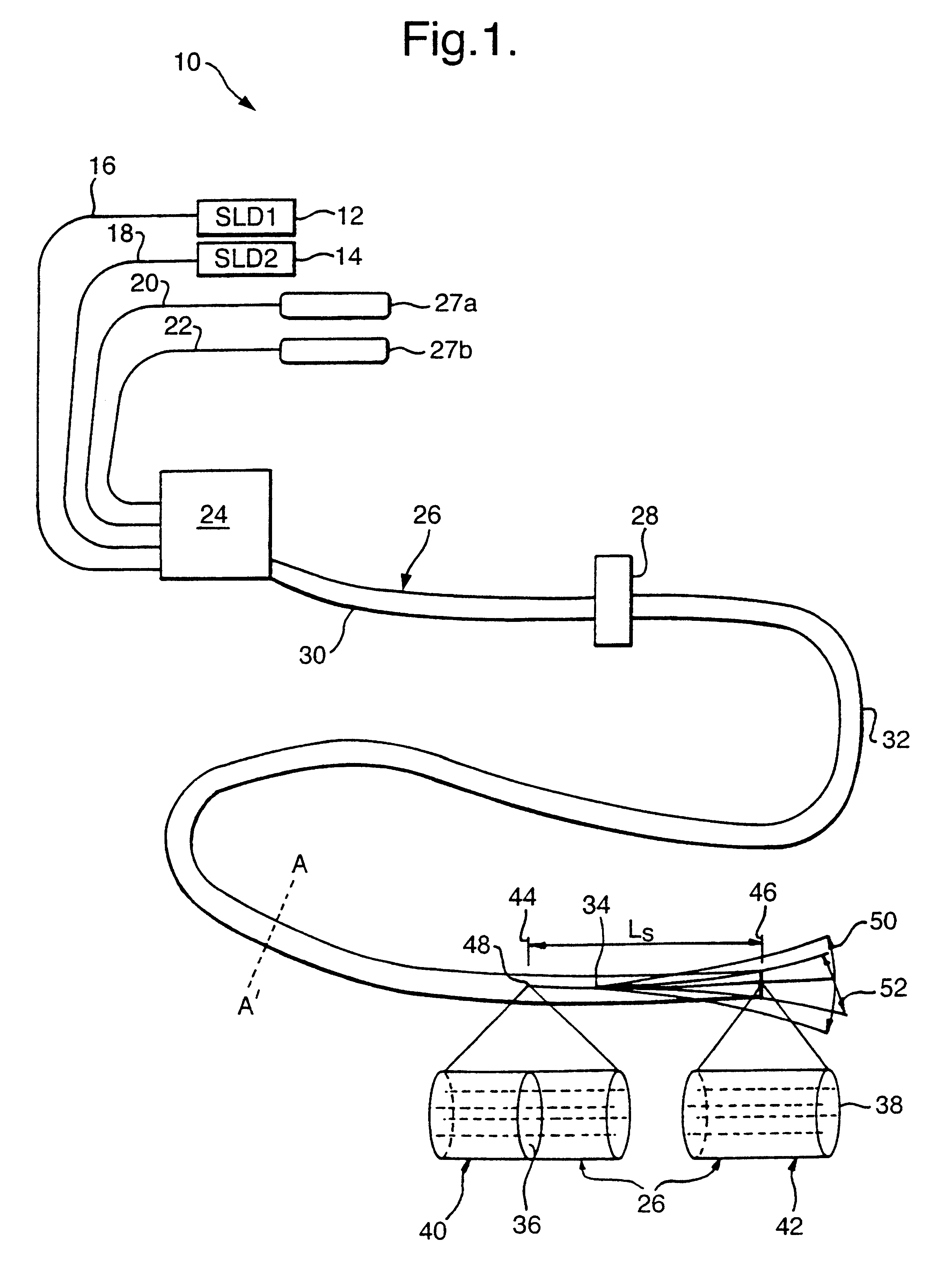
With reference to FIG. 1, an optical fibre bend sensor of the invention for making vector strain measurements is illustrated generally by 10. The sensor 10 incorporates a pair of fibre pigtailed superluminescent diodes 12, 14 connected to a respective pair of input monomode optical fibres 16, 18. Superluminescent diodes (SLDs) are particularly intense sources of broadband radiation. Suitable diodes 12, 14 for use in this invention are supplied by Superlum Ltd., SLD-361 / A-TO-SM, with wavelength range centred at 825 nm and FWHM bandwidth of 18 nm. The input monomode fibres 16, 18 and two output monomode fibres 20, 22 are connected via a fan-out connector 24 to respective cores of a 4-core Bunched Multiple Monomode (BMM) fibre assembly 26. Each output monomode fibre 20, 22 is also connected at its opposite end to a fibre optic linked spectrometer 27a, 27b. Both fan-out connectors and BMM fibres are known and described in Opto and Laser Europe, issue 23, p29 (September 1995). The BMM fi...


PUM


Abstract

An optical fibre bend sensor (10) measures the degree and orientation of bending present in a sensor length (30) portion of a fibre assembly (26). Within a multicored fibre (30, 32,34), cores (62, 66) are grouped in non-coplanar pairs. An arrangement of optical elements (28, 36, 38) define within each core pair (62, 66) two optical paths (122, 124) which differ along the sensor length (30): one core (62) of a pair (62, 66) is included in the first path (122), and the other core (66) in the second path (124). A general bending of the sensor region (30) will lengthen one core (62, 66) with respect to the other. Interrogation of this length differential by means of interferometry generates interferograms from which the degree of bending in the plane of the core pair is extracted. Bend orientation can be deduced from data extracted from multiple core pairs.

Description

1. Field of the InventionThis invention relates to an optical fibre bend sensor.2. Discussion of Prior ArtA deformation of an optical fibre results in strain developing within the fibre. Strains can be categorised depending on the nature of the distortion which produces them. A longitudinal strain: a one-dimensional expansion or compression of the fibre along its length, is categorised as a scalar strain. A scalar strain by its nature requires only one parameter, the magnitude of strain along the axis of the stretch or compression, to characterise it. In terms of the strain tensor (.epsilon.) this longitudinal strain is the tensile component .epsilon..sub.zz.If however a fibre is also free to deform in a transverse plane i.e. that perpendicular to the length of the fibre, further components of the general strain tensor will have effect. If the fibre is restrained in its position, tensile strain (.epsilon..sub.xx, .epsilon..sub.yy) arises within a compressed or stretched fibre in per...

Claims


Application Information

Patent Timeline
Patent Type & Authority Patents(United States)
IPC IPC(8): G01D5/353G01D5/26G01B11/16
CPCG01M11/083G01D5/3538G01D5/35306G01D5/353
Inventor GREENAWAY, ALAN HBURNETT, JAMES GHARVEY, ANDREW RBLANCHARD, PAUL MLLOYD, PETER AMCBRIDE, ROYRUSSELL, PHILIP ST JOHN
Owner OPTASENSE HLDG LTD
Why Eureka
Try Eureka