Combination hydraulic and pneumatic door closer

a technology of hydraulic and pneumatic doors and closers, applied in the field of door closers, can solve the problems of increasing maintenance service costs and oil spill risk, and achieve the effect of reducing costs and maintenance service fees, and eliminating contamination of hydraulic fluid

Active Publication Date: 2017-03-23
CMECH (GUANGZHOU) INDUSTRIAL LTD
View PDF27 Cites 11 Cited by
  • Summary
  • Abstract
  • Description
  • Claims
  • Application Information

AI Technical Summary

Benefits of technology

[0027](3) The use of air for controlling door closing reduces the cost and the maintenance service fee, and eliminates the contamination of hydraulic fluid.

Problems solved by technology

A much longer closing time can cause many problems, for example, the cold air in winter can enter the house easily, or a security flaw will appear.
Moreover, it is difficult for users to adjust the door closer, the above flaws should increase the maintenance service cost and may incur a risk of oil spilling.

Method used


Image

  • Combination hydraulic and pneumatic door closer
  • Combination hydraulic and pneumatic door closer
  • Combination hydraulic and pneumatic door closer

Examples


embodiment 1

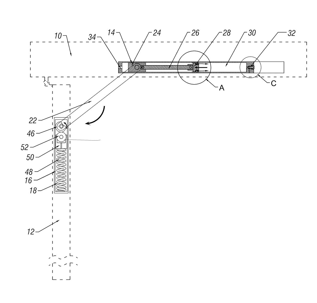
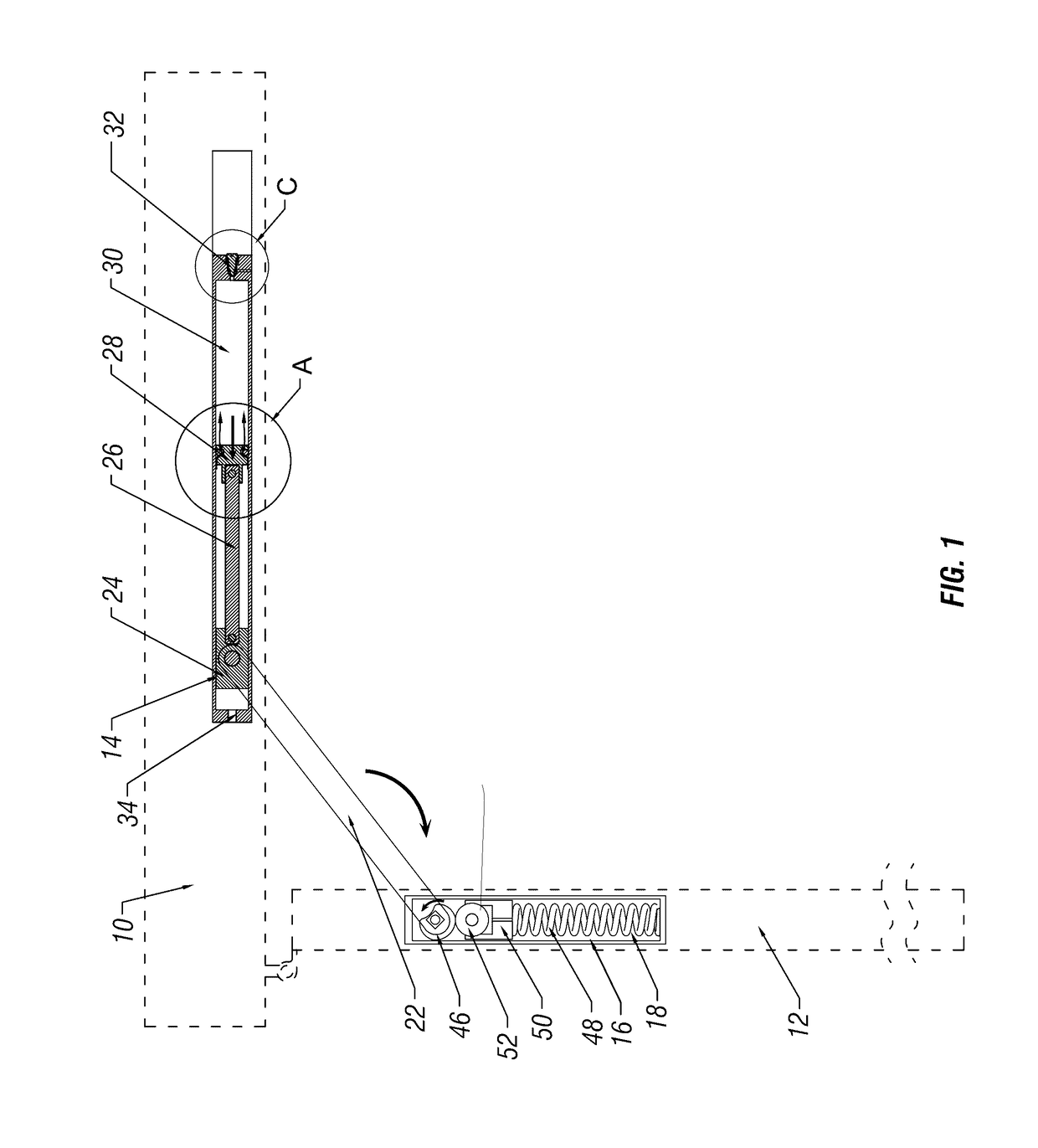
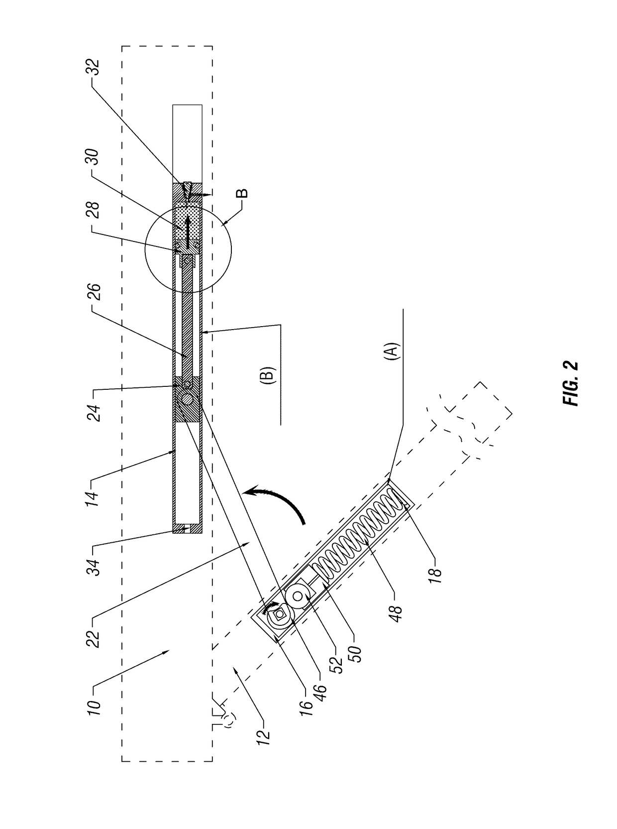
[0080]As shown in the figures a door closer mounted on or in a door frame 10 and a door 12. The closer 10 is capable of adjusting its closing speed, and comprises a pneumatic cylinder 14 mounted in the door frame 10, and a hydraulic cylinder 16 mounted in the door 12. A receiving chamber 18 is formed inside the cylinder 16. A driving apparatus 20 is mounted in the receiving chamber 18. A lever 22 connects the gas adjusting apparatus 24, 26, 28 and the driving apparatus 20.

[0081]A gas adjusting apparatus 24, 26, 28 is provided inside the pneumatic cylinder 14, and comprises a sliding block 24, a piston 28 and a joining rod 26 for connecting the sliding block 24 and the piston 28. A hermetic chamber 30 is formed by the piston 28 at one end of the cylinder 14. A regulating valve 32, for adjusting the exhaust velocity of the hermetic chamber 30, is threadably mounted in the wall of the hermetic chamber 30 at one end of the pneumatic cylinder 14. The other end of the cylinder 14 opposite...

embodiment 2

[0093]As shown in FIG. 1, the structure and work principle in this embodiment are identical to those in Embodiment 1, except for the driving components. In this alternative embodiment, the pulley is a gear 53 and the driving component is a rack 54 engaged with the gear 53. One end of the rack 54 is connected to the spring 48. One end of the lever 22 is hinged to the sliding block 24 while the other end is fixed to the shaft of the gear 53.

[0094]When the door is open, the lever 22 rotates the gear 53, which drives the rack 54 towards the spring 48, thereby the spring 48 possesses a great resilience. When the door 12 is released, the spring 48 drives the rack 54, which rotates the gear 53, such that the lever 22 drives the sliding block 24 towards right side in FIG. 7, whereby the door 12 can close automatically. The counteraction to the piston 28 can be adjusted by adjusting the exhaust of the regulating valve 12, and thereby the closing speed of the door 12 is adjusted.

[0095]In embo...


PUM


Abstract

A door closer capable of adjusting door closing speed, includes a pneumatic cylinder on the door frame, a hydraulic cylinder on the door, and a lever. One end of the lever is movably connected to the pneumatic cylinder, and the other end is connected to the hydraulic cylinder. The pneumatic cylinder includes a sliding rail, and a sliding member cooperated with the sliding rail. A hermetic chamber is formed by the sliding member and the sliding rail. An adjusting valve, for adjusting the air exhaust of the hermetic chamber, is provided on a wall of the hermetic chamber.

Description

CROSS-REFERENCE TO RELATED APPLICATIONS[0001]This application is a continuation-in-part of U.S. application Ser. No. 14 / 795,004 filed Jul. 9, 2015, which in turn claims priority to Chinese Application No. CN 201510318849.8 having a filing date of Jun. 11, 2015 the entire contents of both applications being incorporated by reference.FIELD OF TECHNOLOGY[0002]The following relates to the field of door closers, in particular a door closer capable of adjusting its closing speed.BACKGROUND OF THE INVENTION[0003]The closing speed of a door closer is usually controlled by controlling the flow velocity of oil therein. However, the viscosity of oil varies upon changing temperature, to affect the closing speed of door closers greatly in the regions having big diurnal temperature amplitude, e.g. North America and the North China. It can be known from the experiments, the closing time of a hydraulic door closer is about 8 seconds at 25° C., the closing time is increased to about 2 minutes, which...

Claims


Application Information

Patent Timeline
Patent Type & Authority Applications(United States)
IPC IPC(8): E05F3/02E05F3/10E05F1/10
CPCE05F3/02E05F3/104E05F1/105E05F3/10E05F5/08E05F2003/228E05Y2201/686E05Y2900/132
Inventor FAN, SHUIWANG
Owner CMECH (GUANGZHOU) INDUSTRIAL LTD
Why Eureka
Try Eureka