Electronic disc brake

a technology of electronic disc brake and brake disc, which is applied in the direction of braking elements, noise/vibration control, actuators, etc., can solve the problems of reducing the durability of the actuator, and reducing the noise of the transmission device. , to achieve the effect of reducing the rotational for

Inactive Publication Date: 2017-03-23
HL MANDO CORP
View PDF9 Cites 11 Cited by
  • Summary
  • Abstract
  • Description
  • Claims
  • Application Information

AI Technical Summary

Benefits of technology

[0011]Therefore, it is an aspect of the present disclosure to provide an electronic disc brake in which a connection structure between elements such as a connection unit that transmits a driving force of a motor and a deceleration unit that decreases a rotational force is improved.

Problems solved by technology

However, the plurality of gear devices installed for transmitting power has an adverse effect in terms of operating noise when braking.
For example, an imprecise control of a coupling (an engagement) between gears may cause noise and vibration to be generated when the actuator operates and may degrade a durability of the actuator in more serious cases.

Method used


Image

  • Electronic disc brake
  • Electronic disc brake
  • Electronic disc brake

Examples


Embodiment Construction

[0022]Hereinafter, embodiments of the present disclosure will be described in detail with reference to the accompanying drawings. Embodiments to be introduced below are provided as examples to sufficiently convey the spirit of the present disclosure to those of ordinary skill in the art to which the present disclosure pertains. The present disclosure is not limited to the embodiments to be described below and may also be embodied in other forms. To clearly describe the present disclosure, parts unrelated to the description have been omitted from the drawings, and widths, lengths, thicknesses, and the like of elements in the drawings may be exaggerated for convenience. Like reference numerals refer to like elements throughout.

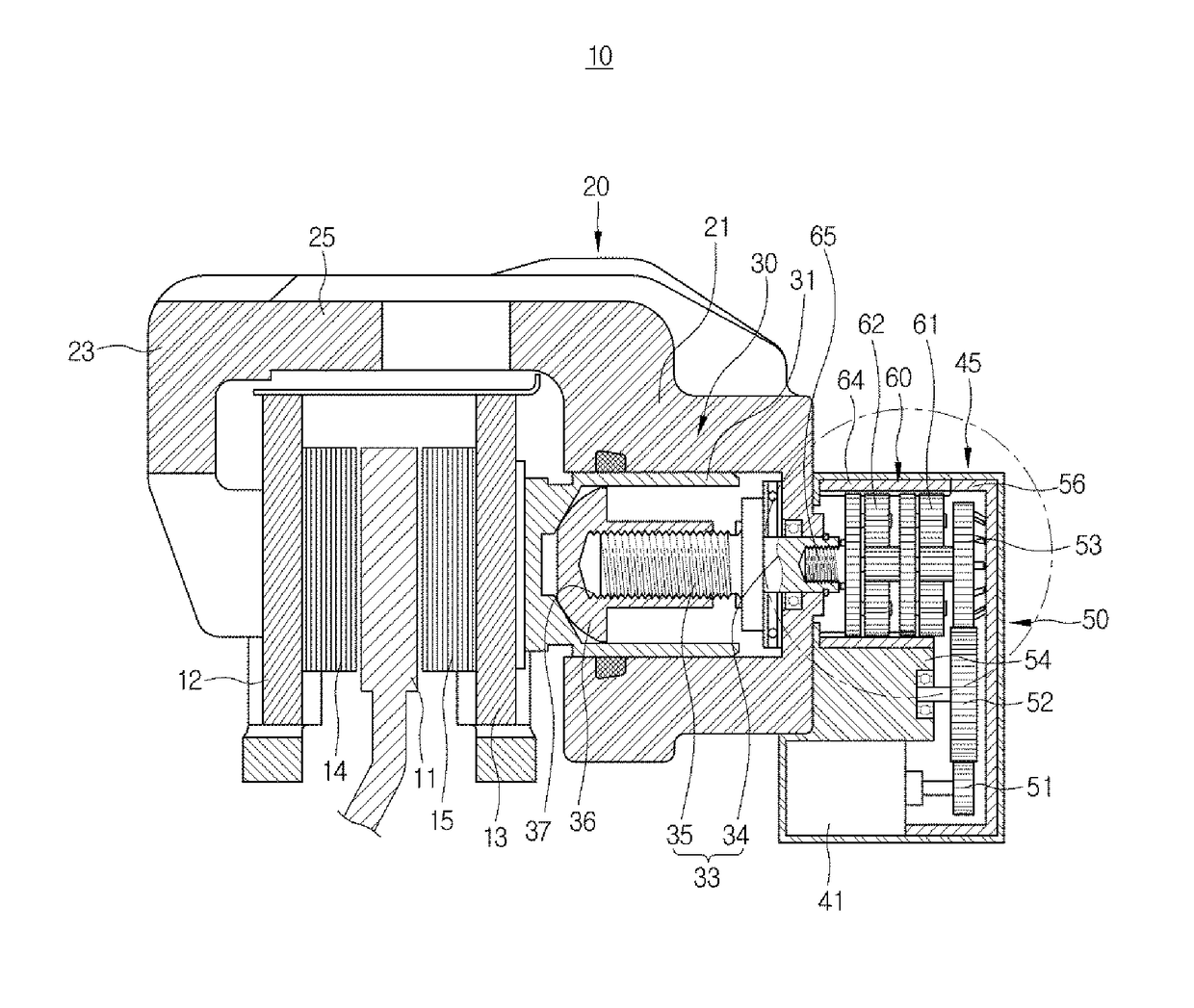
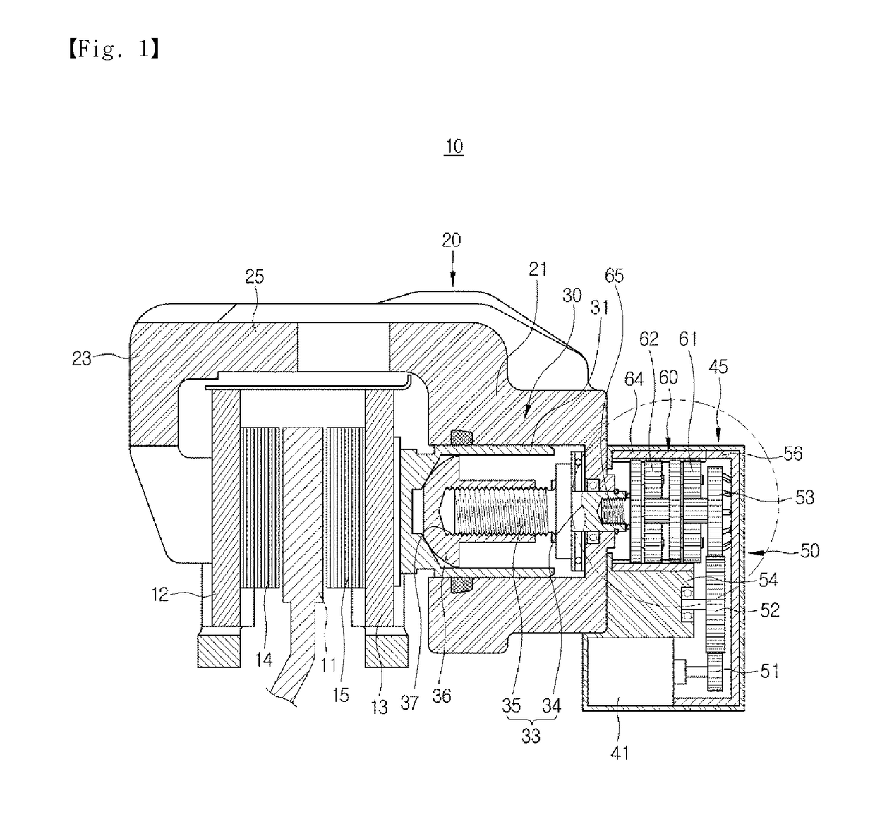
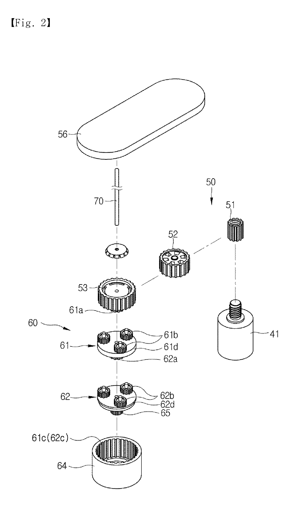
[0023]FIG. 1 is a cross-sectional view illustrating an electronic disc brake according to an embodiment of the present disclosure, and the electronic disc brake illustrated in the drawing is a motor-on-caliper (MOC) type. FIG. 2 is an exploded perspective view o...


PUM


Abstract

Disclosed is an electronic disc brake. The electronic disc brake includes a disc configured to rotate with vehicle wheels, a caliper housing configured to operate pad plates installed at both sides of the disc, and an actuator having a piston provided inside the caliper housing to press the pad plates to adhere the pad plates to the disc, a spindle rotatably installed at the caliper housing to reciprocate the piston, an electric motor configured to rotate the spindle, and a decelerator configured to transmit a rotational force of the electric motor to the spindle. The decelerator includes a power connection unit connected to the electric motor, planetary gear units configured to connect the power connection unit to the spindle, and a center pin configured to pass through the power connection unit and the planetary gear units. The power connection unit includes a driving gear provided at a shaft of the electric motor and a driven gear connected to the planetary gear units. The planetary gear units each include a sun gear, a plurality of planetary gears engaged to an outer portion of the sun gear, a ring gear which is an internal gear configured to accommodate the planetary gears, and a carrier installed to rotatably support the planetary gears and coaxially rotate with the sun gear and configured to and to output a rotational power. The center pin is press-fitted and fixed to the sun gear of the planetary gear unit.

Description

CROSS-REFERENCE TO RELATED APPLICATION[0001]This application claims the benefit of Korean Patent Application No. 2015-0133893, filed on Sep. 22, 2015 in the Korean Intellectual Property Office, the disclosure of which is incorporated herein by reference.BACKGROUND[0002]1. Field[0003]The present disclosure relates to an electronic disc brake, and more particularly, to an electronic brake system capable of realizing a parking function by an operation of an electric motor.[0004]2. Description of the Related Art[0005]Generally, a brake device is a device for stopping a vehicle to prevent the vehicle from moving when the vehicle is braked or parked and serves to hold wheels of the vehicle to prevent the wheels from rotating.[0006]An electronic parking brake (EPB) system that electronically controls an operation of a parking brake is widely used nowadays and is mounted on a typical disk brake to perform a function of the parking brake. Types of electronic disc brakes include a cable pulle...

Claims


Application Information

Patent Timeline
Patent Type & Authority Applications(United States)
IPC IPC(8): F16D65/00F16D65/18F16D55/225
CPCF16D65/0006F16D55/225F16D2125/40F16D2121/24F16D2125/50F16D65/18F16D55/22F16D55/226F16D65/183F16D2121/02F16D2125/48
Inventor SON, JONG-GUKONG, YOUNG-HUN
Owner HL MANDO CORP
Why Eureka
Try Eureka