Device And Method For Geometrically Measuring An Object

a technology for geometric measurement and objects, applied in the direction of instruments, structural/machine measurement, optical properties testing, etc., can solve the problem of not allowing the measurement of thickness

Active Publication Date: 2017-03-23
TAYLOR-HOBSON
View PDF8 Cites 18 Cited by
  • Summary
  • Abstract
  • Description
  • Claims
  • Application Information

AI Technical Summary

Benefits of technology

[0046]According to one development, provision is made for upper and / or lower reference structure or at least one of the surfaces of the object to be scanned with an outer reference structure of the object holder. The outer reference structure is situated on an outer edge or on an outer side of the object holder. Such a method is important, particularly in the case of objects which are not rotationally symmetric. Moreover, this allows a possible lateral offset of the surface images measured in succession in different orientations to be compensated. This also allows the demands in respect of absolutely exact and central bearing of the object on an axis of rotation of the carrier device to be reduced in an advantageous manner.
[0047]According to a further configuration of the method, the scanning of at least one reference structure and of at least one surface of the object is carried out with the same distance measuring device. In this way, it is possible to precisely measure both the reference structure and the surface of the object respectively assigned to the reference structure by means of only a single distance measuring device, which typically comprises the above-described two diametrically oppositely aligned distance sensors. The device-related outlay may be kept within limits in the process.

Problems solved by technology

However, such an apparatus does not allow the measurement of the thickness, in particular a thickness curve or a thickness profile curve over the surface of an object configured in a planar or curved manner, and the determination of the so-called wedge error of lenses.

Method used


Image

  • Device And Method For Geometrically Measuring An Object
  • Device And Method For Geometrically Measuring An Object
  • Device And Method For Geometrically Measuring An Object

Examples


Embodiment Construction

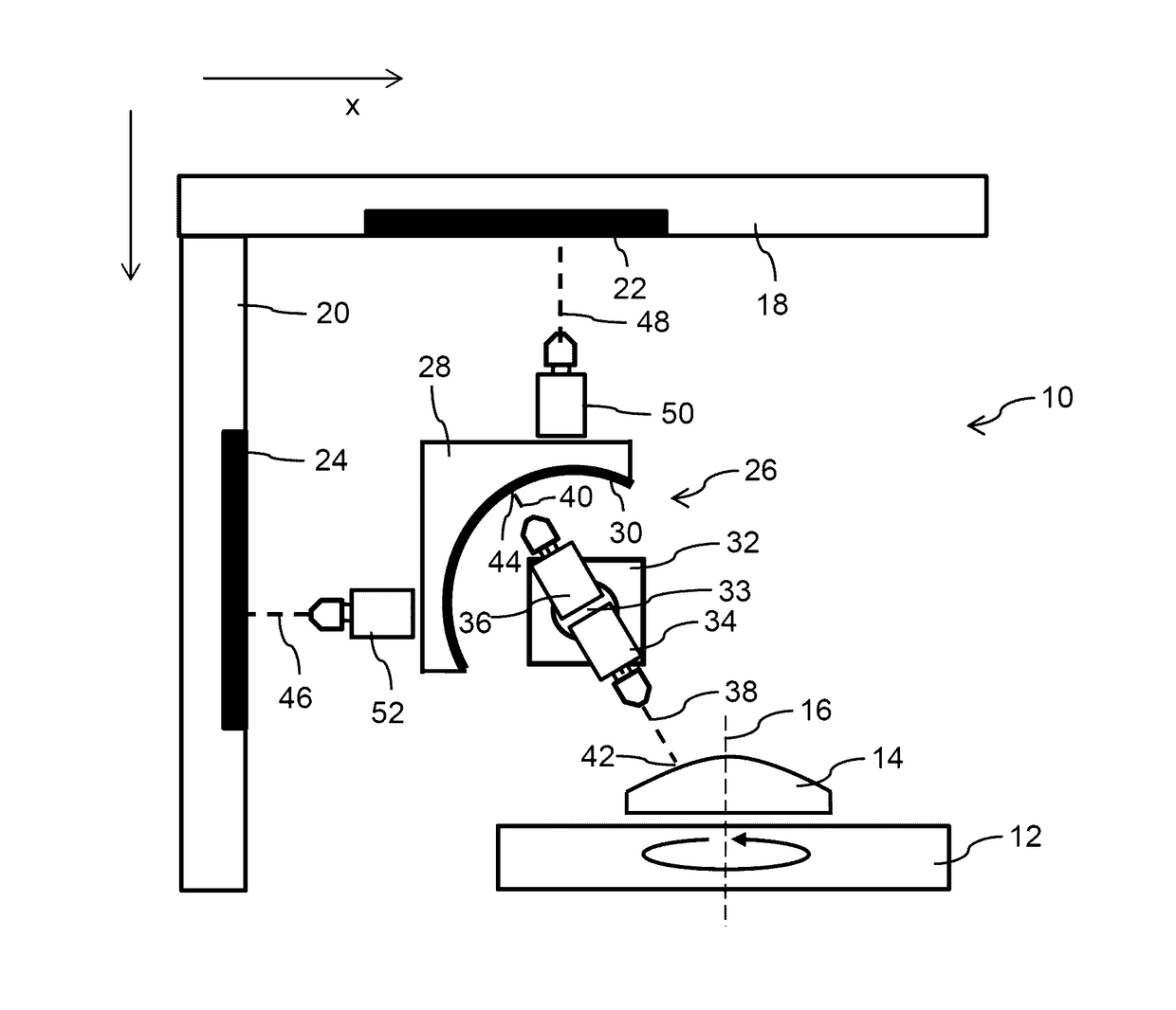
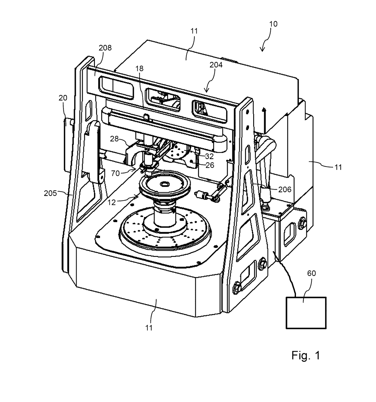
[0075]The measuring apparatus 10 shown in FIGS. 1 to 3 in different illustrations comprises two stationary reference objects 18, 20 which are fixed relative to one another and, in the present case, aligned orthogonal to one another, of which the reference object 18 extends substantially along a first direction (x) and the second reference object 20 extends in a direction (z) perpendicular thereto. Individual reference surfaces 22, 24, which are typically embodied as mirror surfaces or as reflecting surfaces, are provided on both reference objects 18, 20.

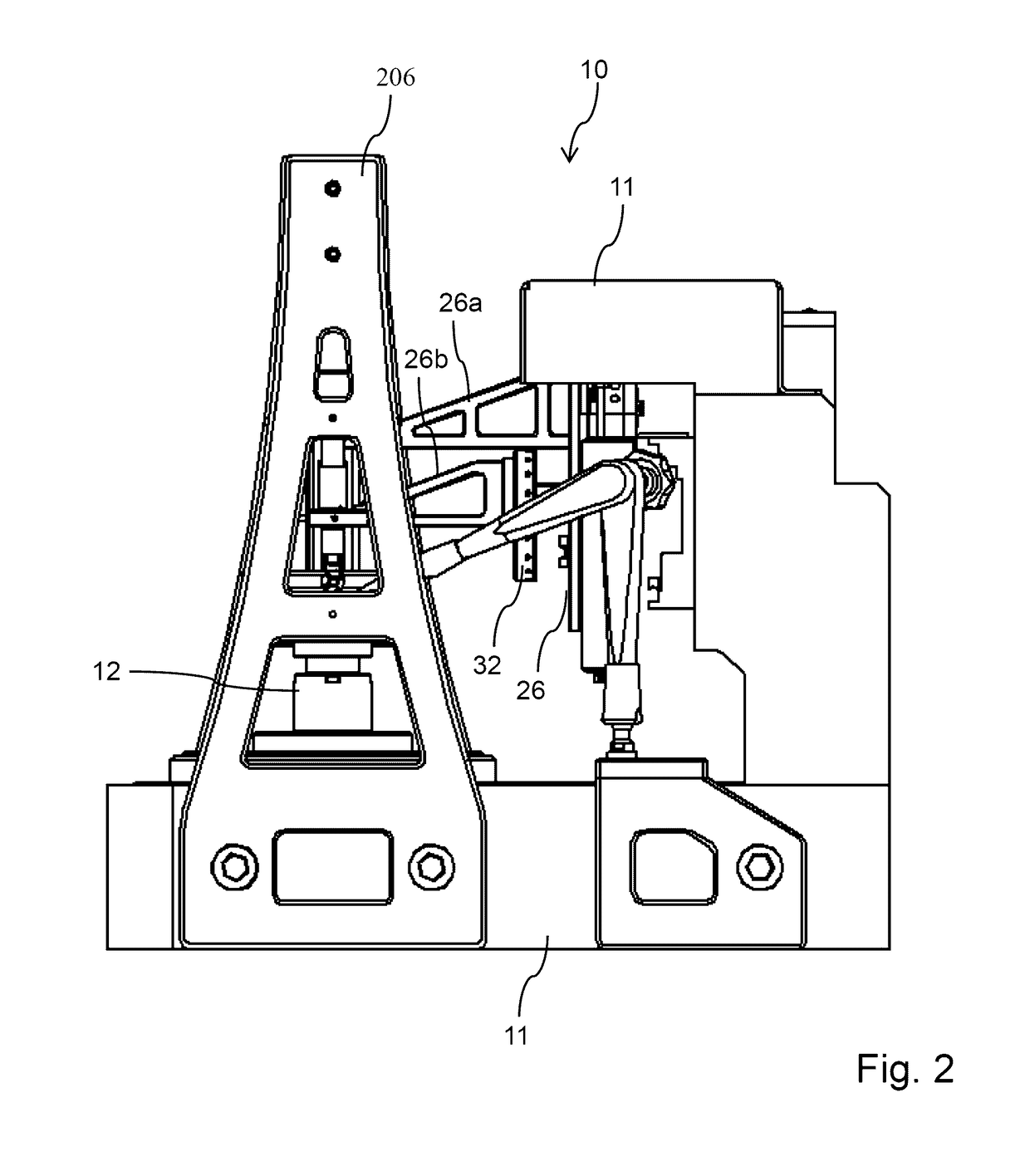
[0076]The apparatus 10 furthermore comprises a rotatably mounted carrier device 12, on which an object 14 to be measured, such as e.g. an optical component, for example a lens 14, is adapted to be arranged and fixable. The carrier device 12 and an object holder 100 fixable thereon in a detachable manner are rotatably mounted about an axis of rotation 16. Furthermore, the measuring apparatus 10 comprises a holder 26 which is movable i...


PUM


Abstract

A device and method for geometrically measuring an object, with a base and a support system arranged thereon for the object, at least one reference object which can be fixed relative to the base, at least one distance measuring system, by means of which a distance between the reference object and the surface of the object facing the reference object can be determined, and an object holder having a top side and an underside, to which the object can be attached, wherein the object holder can be selectively arranged in a first orientation and a second orientation on the support system, wherein the distance measuring system and the object holder are movable relative to each other in order to scan the surface of the object, and the object holder has on the top side thereof and on the underside thereof respective reference structures corresponding to the relative motion of the object holder and to the distance measuring system.

Description

CROSS-REFERENCE TO RELATED APPLICATIONS[0001]This application is the National Stage of International Application No. PCT / EP2015 / 000985 filed on May 13, 2015, which claims the benefit of foreign priority to German Patent Application No. DE 10 2014 007 203.7 filed on May 19, 2014, the entire disclosures of which are hereby incorporated by reference.FIELD OF THE INVENTION[0002]The present invention relates to an apparatus for the geometric measurement of an object, in particular of optical components such as, for example, lenses. The invention moreover relates to a corresponding method and a computer program for the geometric measurement of such objects.BACKGROUND OF THE INVENTION[0003]There is an increasing demand for high-resolution precise measurements of workpieces or, in general, of objects for the purposes of quality assurance and also for monitoring industrial production processes, particularly in the fields of precision engineering, optics and in production technology for mecha...

Claims


Application Information

Patent Timeline
Patent Type & Authority Applications(United States)
IPC IPC(8): G01M11/02G01B11/06G01B11/24
CPCG01M11/025G01M11/0214G01B11/06G01B11/24G01B11/2441G01M11/0221
Inventor MAY, THILOAM WEG, CHRISTIANBERGER, GERNOTNICOLAUS, RALFPETTER, JURGEN
Owner TAYLOR-HOBSON
Why Eureka
Try Eureka