Radar device, signal processing device for radar device and velocity measuring method for radar device

a signal processing and radar technology, applied in measurement devices, using reradiation, instruments, etc., can solve the problems of inability to correctly perform velocity measurement and high computation load, so as to reduce computation load, detect accurate relative velocity, and expand detection velocity range

Active Publication Date: 2017-03-23
FUJITSU GENERAL LTD
View PDF0 Cites 23 Cited by
  • Summary
  • Abstract
  • Description
  • Claims
  • Application Information

AI Technical Summary

Benefits of technology

[0020]According to the present invention, it is possible to provide a technology related to a radar device and making it possible to detect accurate relative velocity even in a case where aliasing of relative velocity has occurred, and expand a detection velocity range. Also, according to the invention, it is possible to provide a technology related to a radar device and capable of reducing an amount of computation during computation of the relative velocity between a target and the radar device.

Problems solved by technology

Therefore, the detection velocity range is determined on the basis of the period of the reception signals, that is, the period of the chirps, and if the relative velocity of the target exceeds the detection velocity range, velocity aliasing occurs, and thus it is impossible to correctly perform velocity measurement.
Also, since the FCM system repeats the FFT process for obtaining the distance as described above, according to the number of chirps, and repeats the FFT process for obtaining the relative velocity, according to the number of range bins, computation load is too high.

Method used


Image

  • Radar device, signal processing device for radar device and velocity measuring method for radar device
  • Radar device, signal processing device for radar device and velocity measuring method for radar device
  • Radar device, signal processing device for radar device and velocity measuring method for radar device

Examples


first embodiment

Configuration of Device

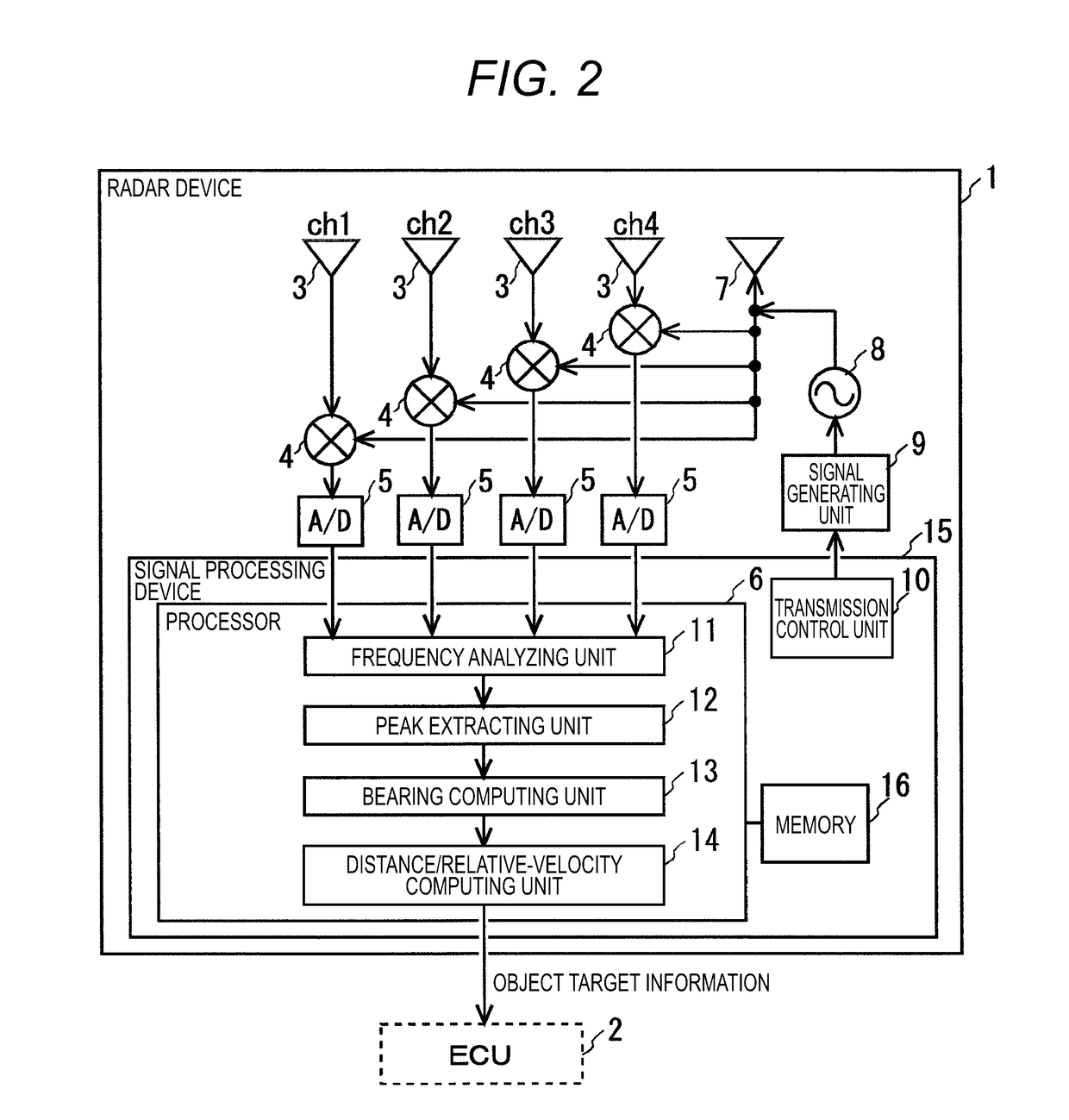
[0047]The radar device 1 includes a transmitting antenna 7, an oscillator 8, and a signal generating unit 9. Also, the radar device 1 includes receiving antennae 3 (ch1 to ch4) arranged at regular intervals, mixers 4 (ch1 to ch4) connected to the receiving antennae 3, respectively, A / D (Analog to Digital) converters 5 (ch1 to ch4) connected to the mixers 4, respectively, and a signal processing device 15 configured to process data of the A / D converters 5.

[0048]Alternatively, the radar device 1 may include a receiving circuit dedicated for each receiving antenna, or may be include a receiving circuit configured to collectively receive reception signals of all receiving antennae. In this case, control for performing switching on the receiving antennae is required such that the receiving antennae sequentially correspond to the receiving circuit in a time division manner; however, it is possible to make the circuit configuration of the radar device 1 compact. In t...

second embodiment

[0095]In the first embodiment, an example in which individual parameters having the same velocity resolution Vmin are used to perform measurement has been described. However, in the present invention, an example in which individual parameters having different velocity resolutions Vmin are used to perform measurement is shown. The present embodiment is the same as the first embodiment in the device configuration of FIG. 2, the flow chart of signal processing of FIG. 5, and the like. Therefore, descriptions of identical elements will not be made, and different elements will be mainly described.

[0096]FIG. 11 shows setting examples of parameters having detection velocity ranges Vmax and velocity resolutions Vmin. In the examples of FIG. 11, with respect to the basic parameter, the detection velocity range Vmax is set to 200 km / h, and the velocity resolution Vmin is set to 1 km / h. Also, with respect to the first parameter, the first detection velocity range V1max is set to 200 km / h, and ...

third embodiment

[0122]In a parameter group including at least the first individual parameter and the second individual parameter, a parameter which is the n-th (wherein “n” is a natural number) is referred to as the n-th parameter. In the above described embodiments, an example in which two individual parameters are used, that is, “n” is 1 or 2 has been described. However, the number of parameters is not limited to two, and three or more parameters may be used to perform measurement. The present embodiment is the same as the first and second embodiments in the device configuration of FIG. 2, the flow chart of signal processing of FIG. 5, and the like. Therefore, descriptions of identical elements will not be made, and different elements will be mainly described.

[0123]In a case of performing velocity measurement by combining a plurality of individual parameters, there are two main integration procedures. A first integration procedure is a procedure of obtaining a relative velocity (hereinafter, also...


PUM


Abstract

There is provided a radar device. A transmitting unit transmits first and second transmission signals generated based on first and second parameters for computing relative velocities in first and second detection velocity ranges, respectively. The second detection velocity range is narrower than the first detection velocity range. A receiving unit receives the reflected waves of the first and second transmission signals from a target as first and second reception signals, respectively. A velocity measuring unit computes first and second relative velocities in the first and second detection velocity ranges based on the first and second reception signals, respectively and obtains the velocity measurement result of the relative velocity of the target based on the combination of the first and second relative velocities.

Description

CROSS-REFERENCE TO RELATED APPLICATIONS[0001]This application is based on and claims priority from Japanese Patent Application No. 2015-184494 filed on Sep. 17, 2015.TECHNICAL FIELD[0002]The present invention relates to a technology related to a radar device for detecting targets, a signal processing device, and a velocity measuring method.RELATED ART[0003]FMCW (Frequency Modulated Continuous Wave) type radar devices are known as radar devices for detecting targets. A FMCW type radar device transmits a transmission signal at a predetermined modulation frequency. If the transmission signal is reflected from a target, the radar device receives the reflected wave, and generates a beat signal representing the deviation between the frequency of the transmission signal and the frequency of the reflected wave. Subsequently, the radar device performs fast Fourier transform on the beat signal, thereby obtaining a frequency spectrum, and performs processing such as maximum peak detection on t...

Claims


Application Information

Patent Timeline
Patent Type & Authority Applications(United States)
IPC IPC(8): G01S13/58G01S13/34G01S7/35G01S13/93G01S13/931
CPCG01S13/584G01S7/352G01S13/343G01S13/931G01S7/356
Inventor MATSUMOTO, TOSHIHIROKAJIKI, JUNKO
Owner FUJITSU GENERAL LTD
Why Eureka
Try Eureka