
Agricultural sprayer boom

a technology for agricultural spraying and booms, which is applied in the direction of load-supporting pillars, mechanical equipment, watering devices, etc., can solve the problems of increasing the length of the boom significantly, increasing the risk of structural failure, and increasing the length of the boom, so as to achieve the effect of improving the resistance to failur

Active Publication Date: 2017-03-30
AGCO INT GMBH
View PDF20 Cites 6 Cited by
  • Summary
  • Abstract
  • Description
  • Claims
  • Application Information

AI Technical Summary

Benefits of technology

The invention provides an agricultural sprayer boom that is stronger and more durable. By using a tubular member with diagonal braces that are gripped instead of welded or pinned, the boom is less likely to fail due to high stress levels. This allows for longer boom sections to be constructed. The tubular member is made of aluminum, which makes the boom stronger without adding much weight. This makes it easier to build and use.

Problems solved by technology

However, increasing the boom length significantly increases the risk of structural failure due to the increased stress placed upon the hinges and joints caused by natural vibrations and oscillations which pass from the spray vehicle along the boom.
Today, boom lengths of conventional truss-style construction are approaching theft physical limits with any further increase in length requiring significant strengthening of the joints, mountings and hinges between sections and along the boom.
Booms having a truss-style construction suffer from peak stresses at the nodes where diagonal brace members are secured to the upper and lower beams.
Conventionally welded joints have been employed to secure the braces but these dictate the structural strength of the overall boom and are known to crack or fail completely under high load conditions.

Method used


Image

  • Agricultural sprayer boom
  • Agricultural sprayer boom
  • Agricultural sprayer boom

Examples


Embodiment Construction

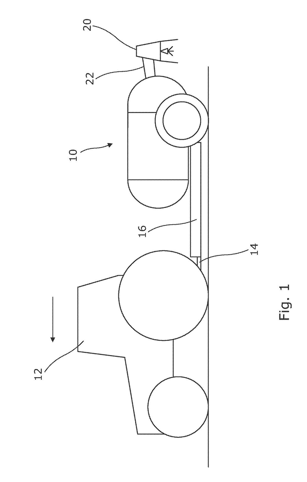
[0026]With reference to FIGS. 1, 2 and 3 a pull-type agricultural sprayer 10 is represented in schematic form from various views. The sprayer 10 is attached to the rear of a tractor 12 by means of towing hitch 14 associated with the tractor and a drawbar tongue 16 forming part of the chassis of the sprayer 10. The sprayer 10 includes a storage tank 18 which serves to store the liquid material to be applied to a crop field.

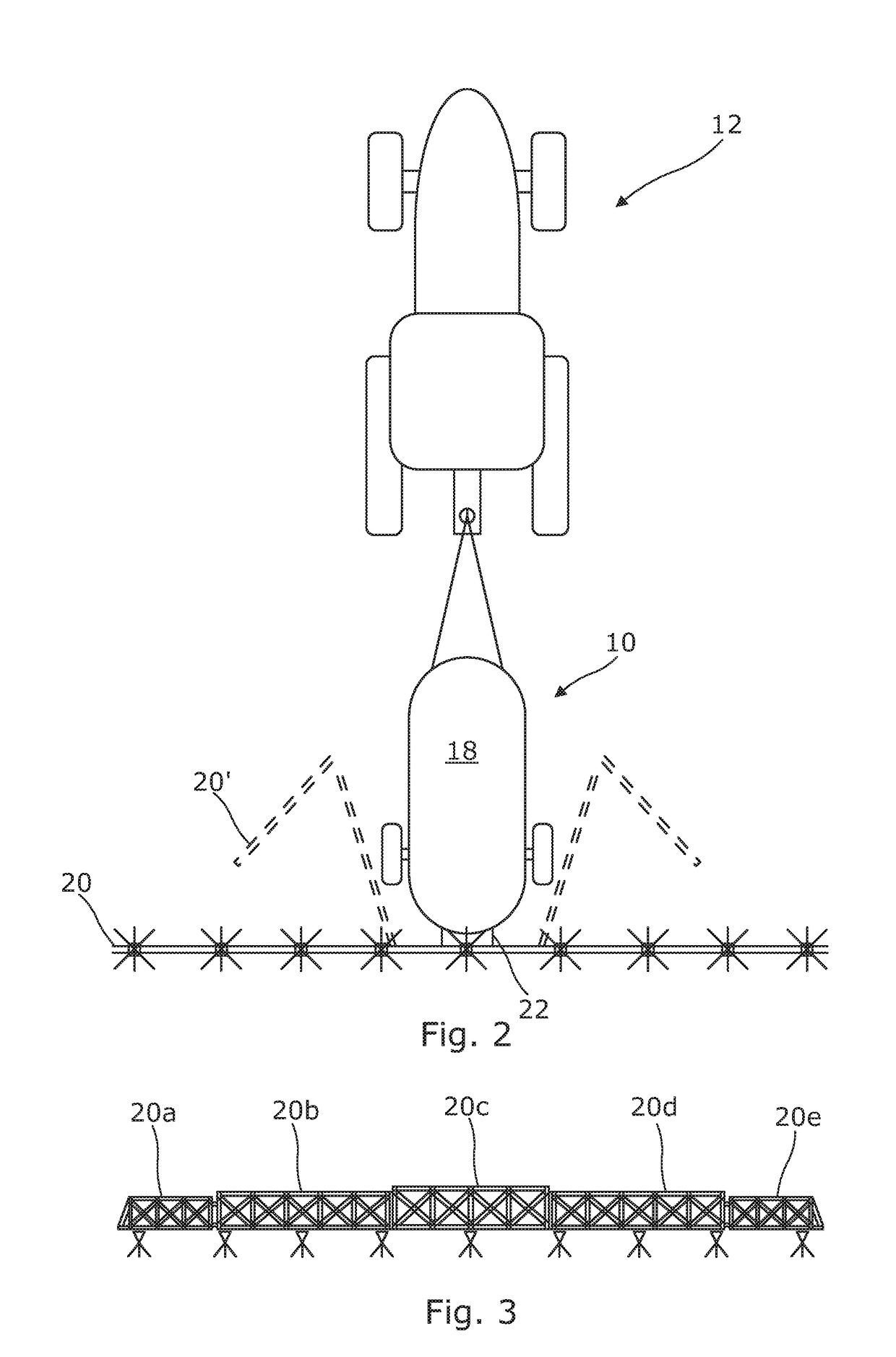
[0027]A transversely-extending multi-section boom 20 is formed from five separate boom sections 20a to 20e which are connected by hinge means and aligned with one another in the operating configuration shown. In this configuration the boom 20 extends substantially at right angles to the forward direction of travel, represented by arrow F in FIG. 1.

[0028]A central boom section 20c is fixed to the rear of the sprayer 10 by a suitable linkage represented at 22. As in known sprayer machines, the linkage 22 may permit raising and lowering of the boom to adapt to differe...


PUM

PropertyMeasurementUnit
lengthaaaaaaaaaa
stressaaaaaaaaaa
lengthsaaaaaaaaaa

Abstract

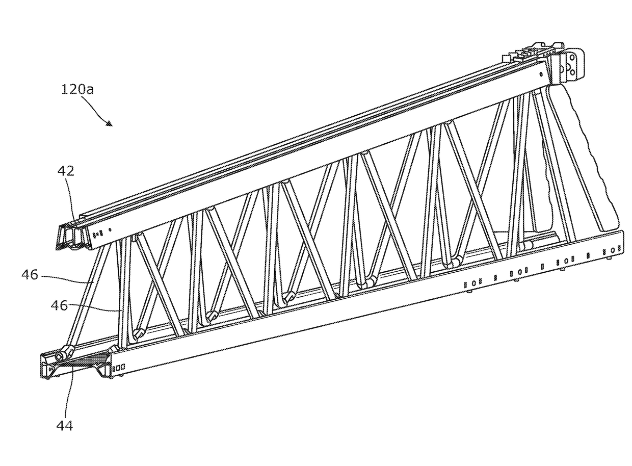
An agricultural sprayer boom comprises vertically spaced upper and lower beams extending along the boom and connected by a plurality of brace membersformed from a unitary bent tubular member that is secured to the upper and lower beams, and gripped, by clamps.

Description

FIELD OF INVENTION[0001]The invention relates to the construction of agricultural sprayer booms and particularly to those employing a truss-based structure having upper and lower beams connected by a plurality of brace members,BACKGROUND[0002]Agricultural sprayers are used by farmers and contractors to apply pesticides and other nutrient-containing solutions to crop fields. Sprayers can be mounted to, or towed by, a tractor or other suitable vehicle or may be self-propelled with an integrated means of propulsion and a drivers cab. The sprayer machine typically includes a storage tank for the liquid to be applied, the tank being filled as required by the operator.[0003]The liquid is applied to the field by a number of liquid application devices, typically spray nozzles, which are mounted in a spaced relationship along the length of a boom which, itself, is mounted to the sprayer vehicle. The nozzles are each connected to the storage tank by liquid delivery means comprising various pi...

Claims


Application Information

Patent Timeline
Patent Type & Authority Applications(United States)
IPC IPC(8): A01M7/00B21D47/01F16L3/16B21C23/14A01C23/00A01G25/09
CPCA01M7/0075A01C23/00B21D47/01F16L3/16B21C23/142A01G25/09A01M7/0071
Inventor HIDDEMA, JORIS JANMERTENS, HARM
Owner AGCO INT GMBH
Learn More