
Adjustable spray head

a spray head and adjustment technology, applied in the field of spray head, can solve the problems of inability to adjust the opening size of the ejecting opening, the difference between the effect of the makeup and the effect expected by the user, and the inability to control the ejecting opening

Inactive Publication Date: 2017-03-30
ZONG JING INVESTMENT
View PDF4 Cites 0 Cited by
  • Summary
  • Abstract
  • Description
  • Claims
  • Application Information

AI Technical Summary

Benefits of technology

The adjustable spray head described in this patent allows for precise control over the timing and concentration of material ejection. It allows for coaxial alignment of the inner and outer tubes, allowing the motive gas and makeup material to be guided into separate channels. The adjusting device can control the needle valve to adjust the opening size and timing of material ejection. Additionally, the outer housing encloses the outer exit, preventing any harm or damage to the material and ensuring it is focused. These technical effects allow for improved spray control and efficiency.

Problems solved by technology

However, the difference in proficiency in the makeup technique and the wide range of cosmetics usually results in a difference between the effect of the makeup and the effect expected by the user.
In use of the spray head, the ejecting opening cannot be controlled to open or to close, or the opening size of the ejecting opening cannot be adjusted.
As a result, the timing, the color, or the concentration of the ejected makeup material cannot be controlled.

Method used


Image

  • Adjustable spray head
  • Adjustable spray head
  • Adjustable spray head

Examples


Embodiment Construction

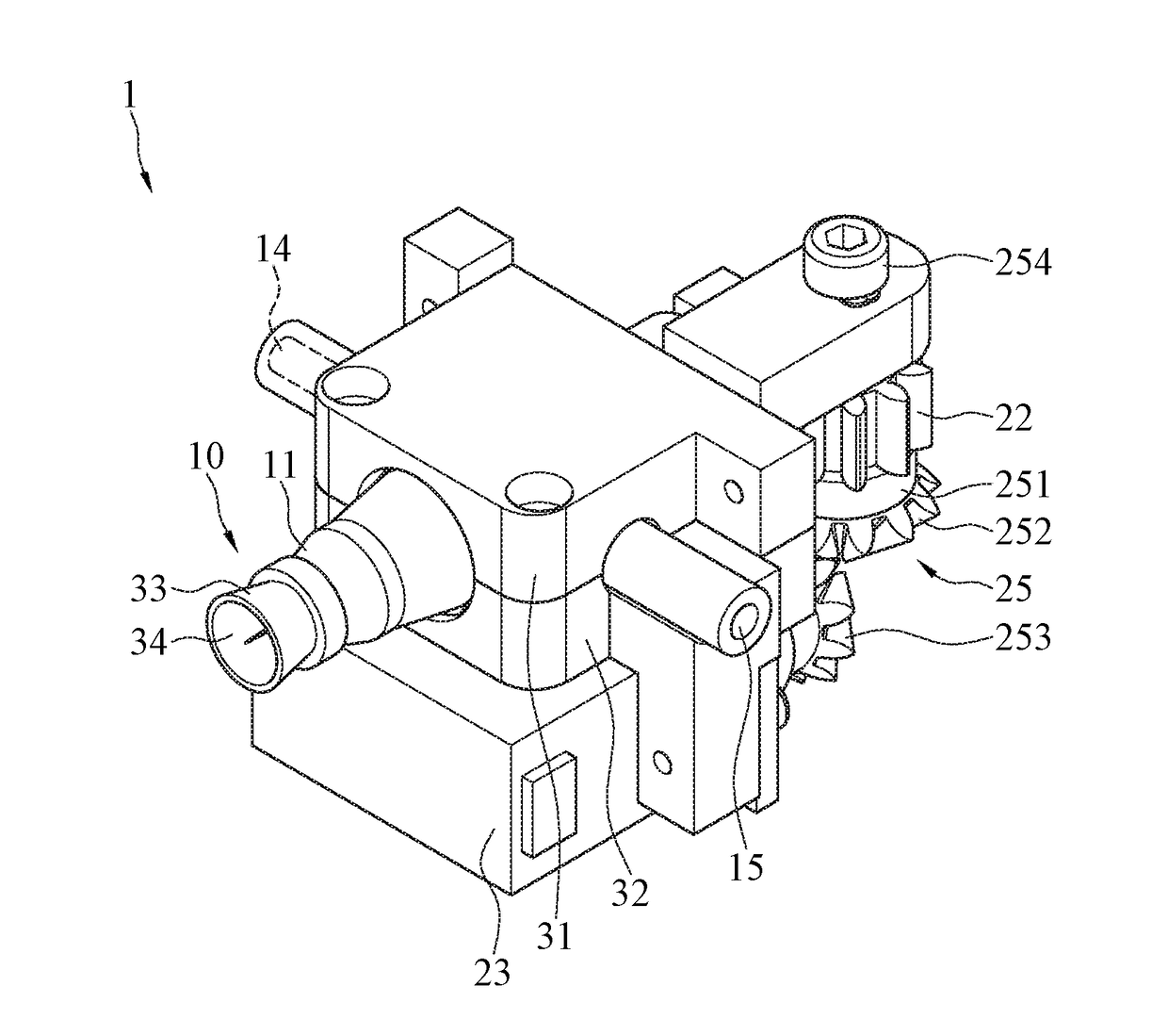
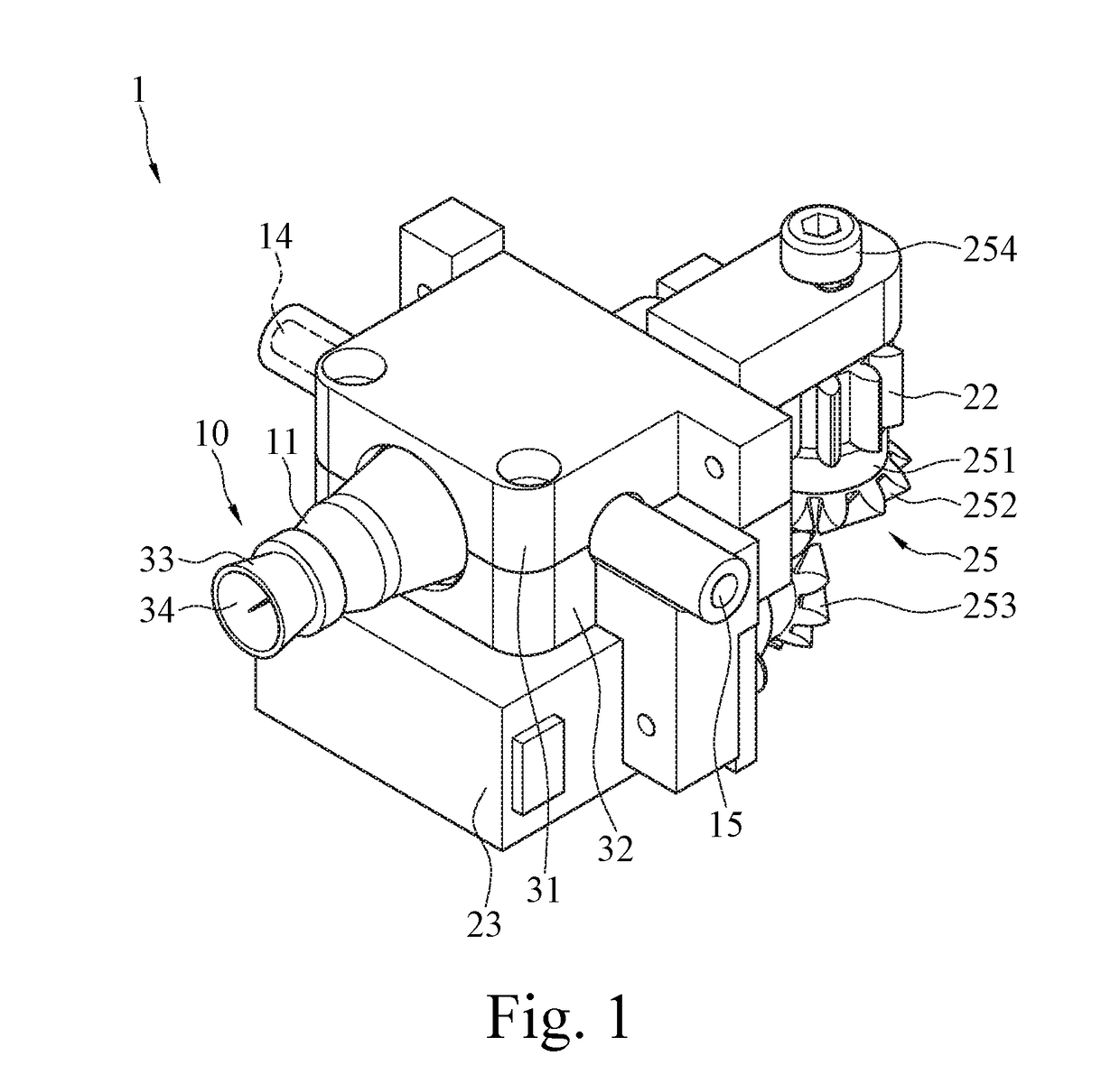
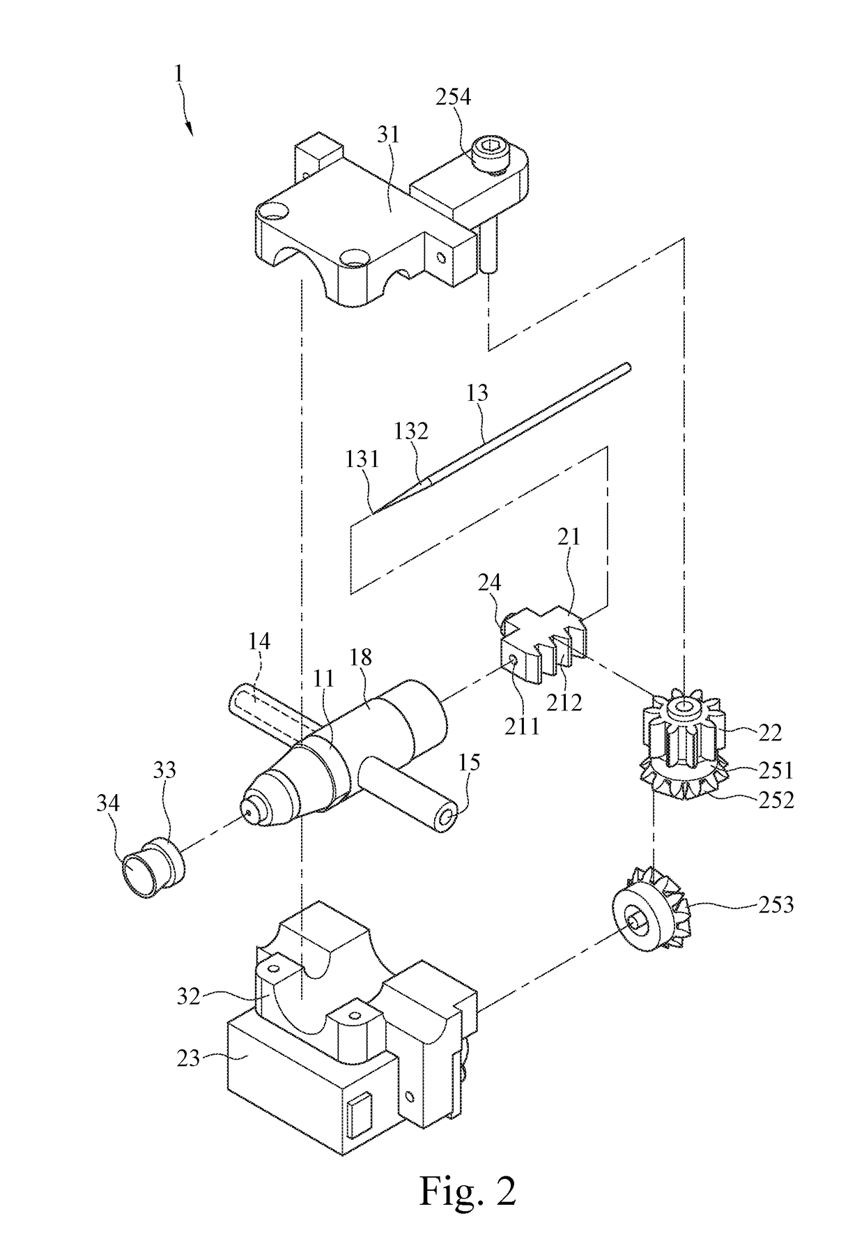
[0026]Please refer to FIGS. 1 to 3, respectively illustrating a perspective view, an exploded view, and a sectional view (1) of an adjustable spray head 1 according to an exemplary embodiment of the instant disclosure. In this embodiment, the adjustable spray head 1 comprises a coaxial spray head 10 and an adjusting device 20.

[0027]In this embodiment, the coaxial spray head 10 comprises an outer tube 11, an inner tube 12, a needle valve 13, a gas inlet 14, and a material inlet 15. The outer tube 11 and the inner tube 12 are approximately round tubular shaped, and the diameter of the outer tube 11 is greater than the diameter of the inner tube 12. The inner tube 12 is coaxially positioned in the outer tube 11. In other words, the coaxial spray head 10 has dual tubes. In this embodiment, a positioning mount 18 is further assembled in the coaxial spray head 10. The positioning mount 18 may be assembled in the coaxial spray head 10 by gluing, buckling, threading, or other means. The pos...


PUM


Abstract

An adjustable spray head includes a coaxial spray head and an adjusting device. The coaxial spray head includes an outer tube, an inner tube, a needle valve, a gas inlet, and a material inlet. The inner tube is coaxially positioned in the outer tube. One end of the outer tube has an outer exit. The needle valve is coaxially positioned in the inner tube. One end of the inner tube has an inner exit. The top end of the needle valve can be inserted into the inner exit. The adjusting device includes a clamping member, a transmission gear, and a driving motor. The clamping member includes a clamping portion and a teeth bar. The clamping portion clamps the needle valve. The teeth bar is engaged with the transmission gear. The driving motor drives the transmission gear to rotate to drive the clamping member to move linearly.

Description

CROSS-REFERENCES TO RELATED APPLICATIONS[0001]This non-provisional application claims priority under 35 U.S.C. §119(a) on Patent Application No. 104215619 filed in Taiwan, R.O.C. on 2015 Sep. 25, the entire contents of which are hereby incorporated by reference.BACKGROUND[0002]Technical Field[0003]The instant disclosure relates to a spray head, in particular, to an adjustable spray head.[0004]Related Art[0005]Nowadays, people pay more attention to their life qualities. When a person is going to work, hangout, or attend a meeting, he or she not only cares about the dress, but also his or her facial look. Consequently, numerous cosmetics for customers have appeared. Nevertheless, to apply a proper facial makeup or an eye makeup, the user must repeatedly practice the makeup skills. Furthermore, drawing various eyebrow shapes, eye contours, eye lines, and eye shadows, etc., requires the purchase of many kinds of cosmetics and makeup tools. However, the difference in proficiency in the m...

Claims


Application Information

Patent Timeline
IPC IPC(8): A45D34/04B05B1/30B05B7/04B05B7/12A45D40/26A45D44/00
CPCA45D34/04A45D40/26B05B1/3013B05B7/0416B05B7/12A45D44/005A45D2200/057
Inventor CHEN, JOHNFAN, CHIH-KUN
Owner ZONG JING INVESTMENT
Learn More