
Apparatus and method for wavefront guided vision correction

a wavefront sensor and guided vision technology, applied in the field of wavefront sensors, can solve the problems of bulky bulky wavefront sensors for measuring the aberration of the human eye, and achieve the effect of improving the accuracy of the measuremen

Inactive Publication Date: 2017-03-30
CLARITY MEDICAL SYST
View PDF0 Cites 7 Cited by
  • Summary
  • Abstract
  • Description
  • Claims
  • Application Information

AI Technical Summary

Benefits of technology

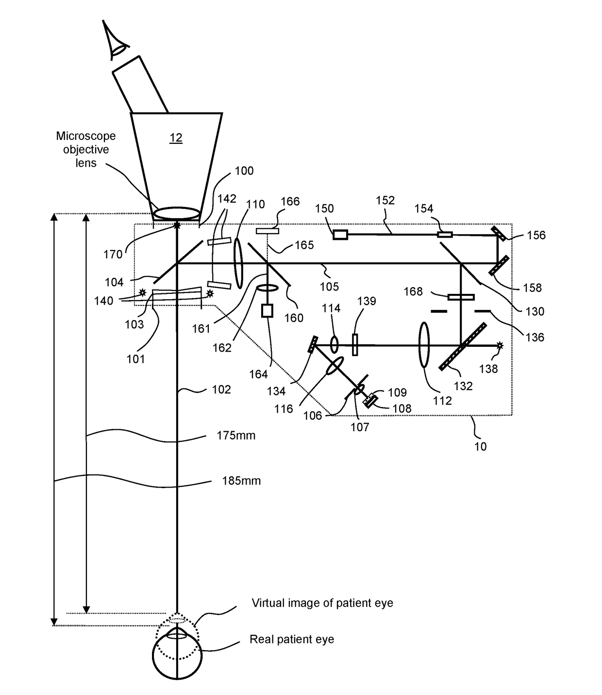
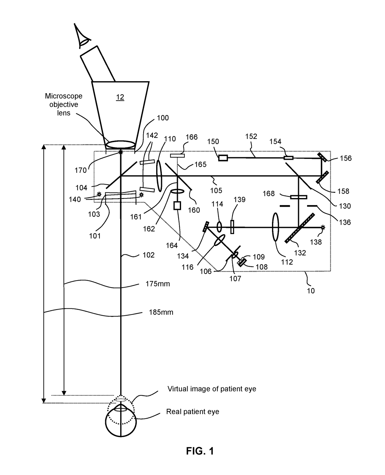
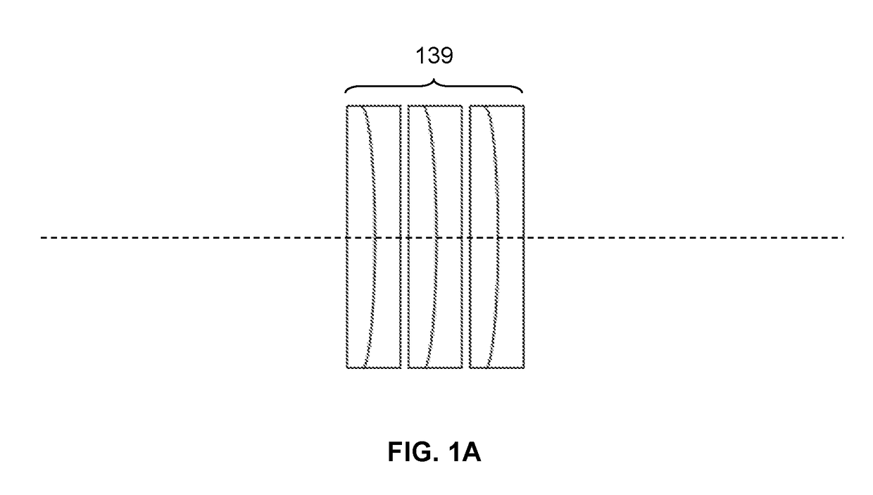
This patent describes the use of a lens in a wavefront sensor module of an ophthalmic microscope to provide flexibility in adjusting the microscope's working distance for a surgeon and to partially or fully compensate astigmatism that can be introduced to the microscope or the wavefront sensor. The tilting of the front lens of the wavefront relay helps to reduce optical noise and improve wavefront measurement accuracy and precision over a large diopter range. Additionally, the patent also describes the use of at least two stacked dynamic focus variable lenses to null or compensate the sphere component of the object wavefront from a patient eye.

Problems solved by technology

Currently, most wavefront sensors for measuring the aberration of a human eye are bulky and are designed to only cover a limited diopter range of about −20D to +20D for a phakic or pseudo-phakic eye.

Method used


Image

  • Apparatus and method for wavefront guided vision correction
  • Apparatus and method for wavefront guided vision correction
  • Apparatus and method for wavefront guided vision correction

Examples


Embodiment Construction

[0028]Reference will now be made in detail to various embodiments of the invention. Examples of these embodiments are illustrated in the accompanying drawings. While the invention will be described in conjunction with these embodiments, it will be understood that it is not intended to limit the invention to any embodiment. On the contrary, it is intended to cover alternatives, modifications, and equivalents as may be included within the spirit and scope of the invention as defined by the appended claims. In the following description, numerous specific details are set forth in order to provide a thorough understanding of the various embodiments. However, the present invention may be practiced without some or all of these specific details. In other instances, well known process operations have not been described in detail in order not to unnecessarily obscure nor apply limitations to the present invention. Further, each appearance of the phrase an “example embodiment” at various place...


PUM


Abstract

Considered herein is a real time wavefront sensor and system to provide live feedback for various vision correction procedures such as LRI / AK refinement, Laser Enhancement, and cataract / refractive surgery, designed to reduce or eliminate interference during an examination and / or a surgical operation. Wavefront sensor modules attached to microscopes can reduce the available working space or working distance for an operator or surgeon. Use of a negative lens, rather than a non-lens optical shield or window, can increase in the working distance for an operator or surgeon to, at least in part, compensate for any reduction in the working space as a result of the attachment of the wavefront sensor module to the microscope.

Description

CROSS-REFERENCE TO RELATED APPLICATIONS[0001]The present application claims benefit of priority to U.S. Provisional Application No. 62 / 222,937 entitled “APPARATUS AND METHOD FOR WAVEFRONT GUIDED VISION CORRECTION” and filed on Sep. 24, 2015, the entirety of which is incorporated by reference herein.TECHNICAL FIELD OF THE INVENTION[0002]One or more embodiments of the present invention relate generally to wavefront sensors for determining the refractive state and / or wavefront aberrations of an eye and methods for wavefront guided vision correction.BACKGROUND OF THE INVENTION[0003]Optical wavefront sensors are devices used to measure the shape of a wavefront of light (see, for example, U.S. Pat. No. 4,141,652 and U.S. Pat. No. 5,164,578). In most cases, a wavefront sensor measures the departure of a wavefront from a reference wavefront or an ideal wavefront such as a planar wavefront. A wavefront sensor can be used for measuring both low order and high order aberrations of various opti...

Claims


Application Information

Patent Timeline
IPC IPC(8): A61B3/10G02B13/00G02B27/00G02B27/10
CPCA61B3/1015G02B27/0068G02B13/0095G02B27/108G02B26/06
Inventor ZHOU, YANPON, RUSSELLLINDER, BARRY
Owner CLARITY MEDICAL SYST
Learn More