
Three-dimensional dynamic focusing lens group, optical lens, laser processing equipment and method

A three-dimensional dynamic lens group technology, applied in the field of optics, can solve problems such as low work efficiency, large installation space, and uncompact lens group structure, and achieve the effects of easy design, change of working distance, and high concentration of laser energy

Active Publication Date: 2021-06-18
HANS LASER TECH IND GRP CO LTD
View PDF3 Cites 0 Cited by
  • Summary
  • Abstract
  • Description
  • Claims
  • Application Information

AI Technical Summary

Problems solved by technology

Among them, the distance between the second curved surface and the third curved surface on the optical axis ranges from 60mm-70mm, which is relatively large and takes up a large installation space, making the structure of the lens group not compact, and the working distance of the F-Theta lens is between 245mm- Change within 270mm, relatively short, when used to process large workpieces with a large working distance, repeated operations are required, and the work efficiency is low

Method used


Image

  • Three-dimensional dynamic focusing lens group, optical lens, laser processing equipment and method
  • Three-dimensional dynamic focusing lens group, optical lens, laser processing equipment and method
  • Three-dimensional dynamic focusing lens group, optical lens, laser processing equipment and method

Examples


Embodiment Construction

[0026] In order to make the object, technical solution and advantages of the present invention clearer, the present invention will be further described in detail below in conjunction with the accompanying drawings and embodiments. It should be understood that the specific embodiments described here are only used to explain the present invention, not to limit the present invention.

[0027] It should be noted that the terms "setting" and "connecting" should be understood in a broad sense, for example, they can be directly set and connected, or indirectly set and connected through a central component or a central structure.

[0028] In addition, if there are "length", "width", "thickness", "upper", "lower", "front", "back", "left", "right", "vertical", "Horizontal" and other terms indicating orientation or positional relationship are based on the orientation or positional relationship shown in the drawings or the conventional placement state or use state, which are only for the ...


PUM

PropertyMeasurementUnit
emission peakaaaaaaaaaa
wavelengthaaaaaaaaaa

Abstract

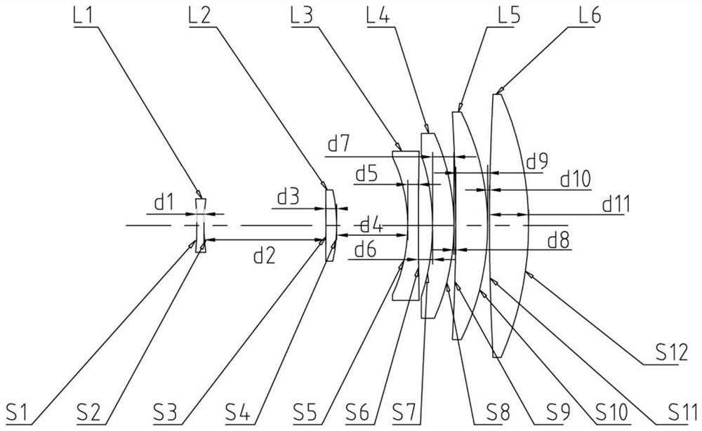
The invention is applicable to the field of optical technology, and discloses a three-dimensional dynamic focusing lens group, an optical lens, laser processing equipment and a method. The three-dimensional dynamic focusing lens group includes a dynamic lens group and a fixed lens group. The dynamic lens group includes a first lens and a second lens that moves relative to the position of the first lens. The first lens is a biconcave negative lens, and the second lens is a flat lens. Convex positive lens, the fixed lens group includes the third lens, the fourth lens, the fifth lens and the sixth lens, the third lens is a biconcave negative lens, the fourth lens and the fifth lens are lunar positive lenses, and the sixth lens is Double convex positive lens, the first lens to the sixth lens are arranged in sequence along the direction from the object side to the image side, the central axes of the first lens to the sixth lens are located on the optical axis, and the relative distance between the first lens and the second lens on the optical axis The position change is 29.3mm-40.75mm, and the focal point of the light passing through the dynamic lens group and the fixed lens group in turn changes within 272.5mm-332.5mm. The invention can realize three-dimensional high-quality imaging marking, and improves the imaging quality.

Description

technical field [0001] The invention belongs to the field of optical technology, and in particular relates to a three-dimensional dynamic focusing lens group, an optical lens, laser processing equipment and a method. Background technique [0002] With the development of industrial lasers, people's technical requirements for industrial laser applications are also getting higher and higher. Especially in complex parts and complex environments, ordinary engraving and marking can no longer meet the needs. Three-dimensional dynamic laser application system also came into being. Its appearance is a new breakthrough in the field of laser application. Compared with the traditional two-dimensional laser marking machine, the advantages of the three-dimensional dynamic focusing three-dimensional laser marking system are very obvious. It can not only realize large-format laser marking processing, but also perform multi-dimensional three-dimensional marking or engraving on complex par...

Claims


Application Information

Patent Timeline
Patent Type & Authority Patents(China)
IPC IPC(8): G02B7/10G02B15/167B23K26/06
CPCG02B7/10G02B15/167B23K26/0648
Inventor 陈玉庆彭金明周朝明高云峰
Owner HANS LASER TECH IND GRP CO LTD
Learn More