Wire electric discharge machine

a discharge machine and wire technology, applied in the direction of electrical circuits, manufacturing tools, electrical-based machining electrodes, etc., can solve the problems of inability to accurately correct the dimensions of the rework, the process requires many man-hours and skill, and the rework cannot solve the problem of accurate rework, etc., to achieve accurate dimension measurement, less contraction and deviation, and the effect of small deviation

Active Publication Date: 2017-03-30
FANUC LTD
View PDF5 Cites 11 Cited by
  • Summary
  • Abstract
  • Description
  • Claims
  • Application Information

AI Technical Summary

Benefits of technology

[0011]In view of the above problem inherent in the prior art, an objective of the present invention is to provide a wire electric discharge machine having a function of measuring a workpiece remain immersed in a working fluid by means of a touch probe, and capable of a more accurate dimension measurement by causing the contraction and expansion of a workpiece and a table of metal material due to temperature variation hard to occur, so that there is substantially no deviations between the position and dimensions obtained by machining in a working fluid, and those at the time of measurement.
[0014]According to the wire electric discharge machine of the present invention as described above, even when the workpiece is immersed only on the lower surface thereof, the measurement accuracy can more stably be achieved with respect to that not immersed at all and started to dry. The object of the present invention can partially be achieved only by immersing to the upper surface of the table, since the table will dry and surely be deformed unless the leg or legs of it is immersed.
[0019]In accordance with the present invention, a wire electric discharge machine can be provided having a function of measuring with a touch probe a workpiece remain immersed in a working fluid, and capable of a more accurate dimension measurement by causing less contraction and expansion of a workpiece and a table of metal material under the effect of temperature variation, so that there is little deviation between the position and dimensions obtained by machining in a working fluid, and those at the time of measurement.

Problems solved by technology

However, when dimensional error is found after measurement, it is necessary to rework the part for the correction of the error.
This process requires many man-hours and skill.
If remount of the detached workpiece for rework is failed, the dimensions cannot be corrected accurately by the rework.

Method used


Image

  • Wire electric discharge machine
  • Wire electric discharge machine
  • Wire electric discharge machine

Examples


embodiment 1

When Machining

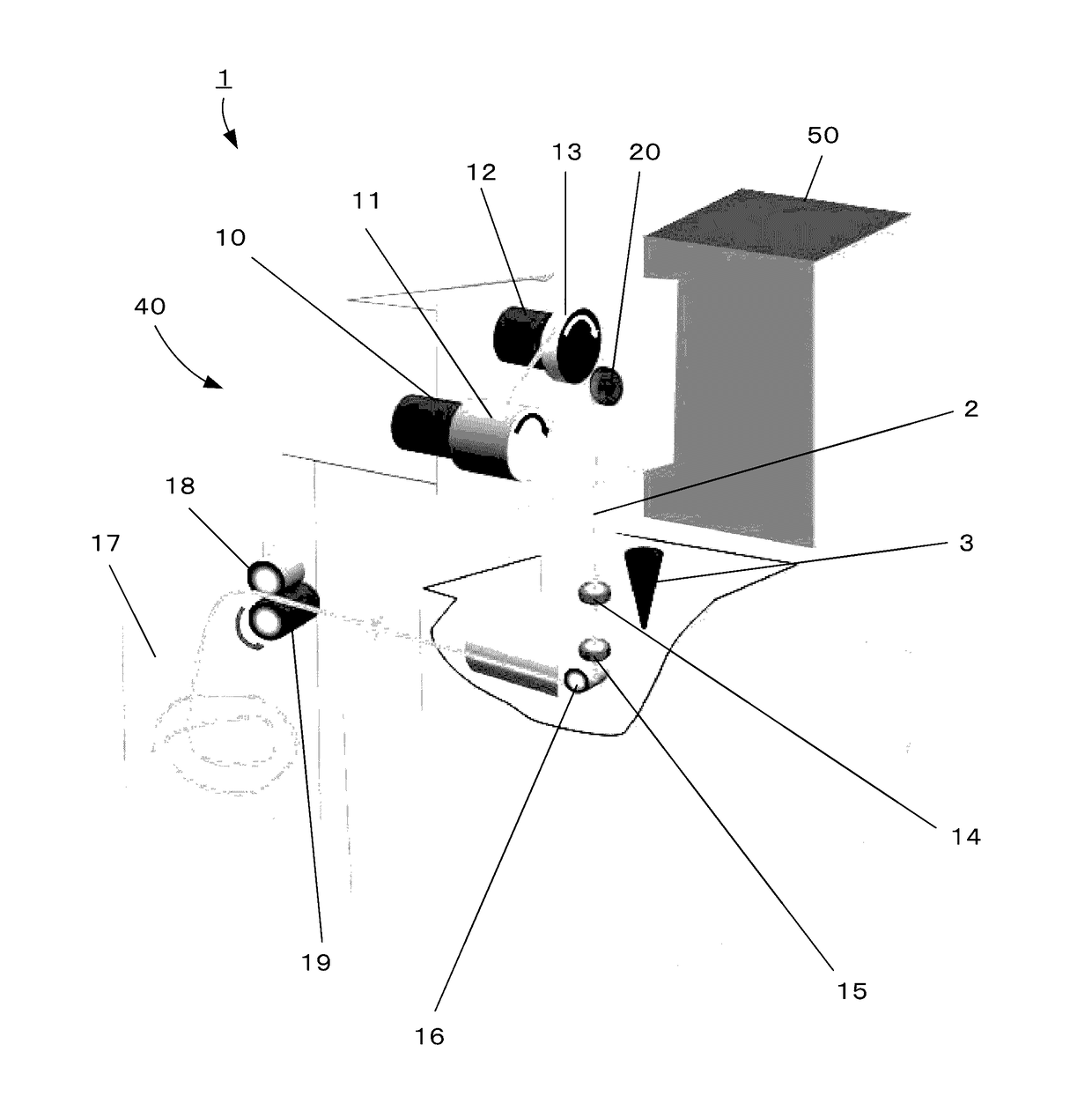
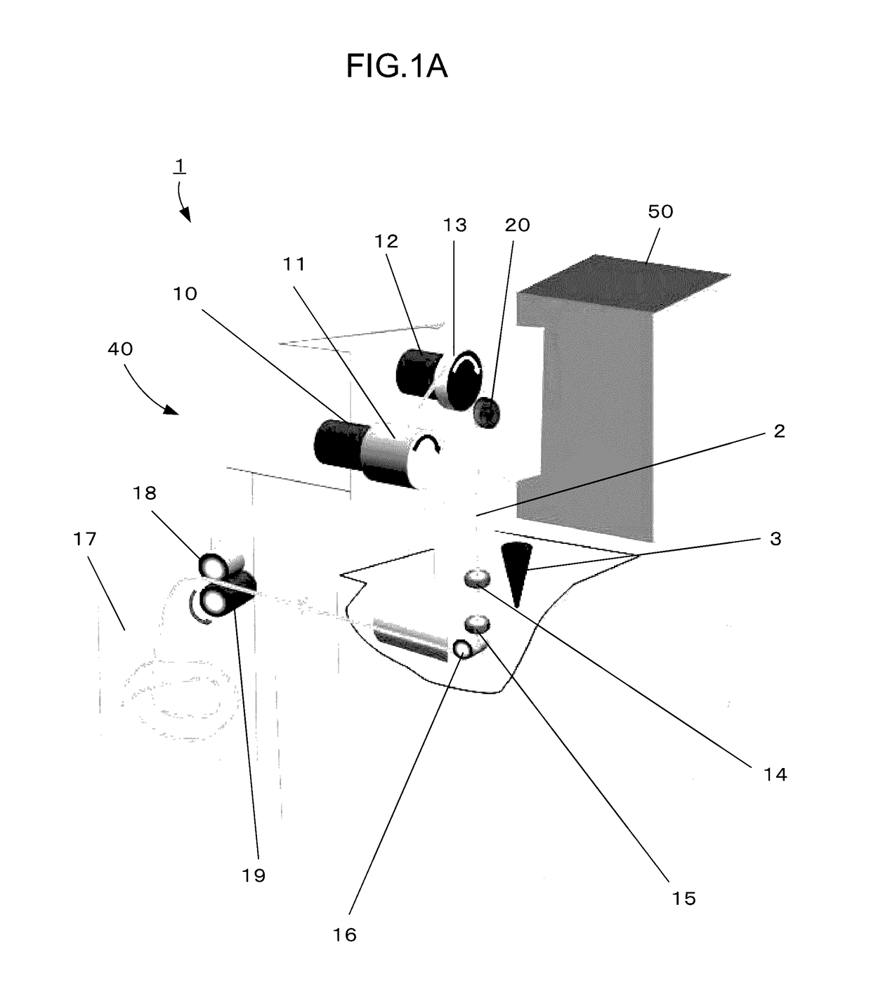
[0060]FIG. 5 is a diagram illustrating the principle for controlling the level upon machining a workpiece 26 by a wire electric discharge machine 1.

[0061]The level is automatically adjusted in conjunction with a upper guide height L1 upon machining, to a level (working fluid level L3 measured by hydraulic pressure sensor 25) where an upper guide part 21 can be sufficiently submerged in a working fluid 4 to prevent splashing of the working fluid 4 and to remove the heat energy produced by supplying the electricity to the upper guide part 21 (i.e. for cooling the feeder), while the upper guide part 21 is brought close to a workpiece upper surface 26a. To avoid interference of the sensor of a touch probe 3 with the workpiece 26 and submergence of the body, the touch probe 3 is driven by a holding part 22 to move in a probe rising direction 30, and is positioned ascendant with respect to the upper guide part 21. The touch probe 3 may be detached from the wire electric disc...

embodiment 2

When Machining

[0068]The steps effected upon working are the same as those explained in the description of the first embodiment so that no explanation are made to avoid the duplication.

(When Measuring)

[0069]FIG. 9 is a diagram illustrating the principle for controlling upon measurement in Embodiment 2. When measuring, an upper guide part 21 is raised (see reference numeral 31), and a touch probe 3 is positioned in a lowered position (see reference numeral 32), or the probe 3 is attached to the upper guide part 21. Then, a level detector such as a hydraulic pressure sensor 25, and a working fluid supply device and discharge device automatically adjust the level of a working fluid, to a position where a lower surface of a workpiece 26 is immersed, and a table 24 and an unillustrated workpiece attachment jig attached between the workpiece 26 and the table 24 are completely submerged. That is, by using preset information on the high L2 of the upper surface of the table on which the workp...

embodiment 3

When Machining

[0074]The steps effected upon working are the same as those explained in the description of the first embodiment so that no explanation are made to avoid the duplication.

(When Measuring)

[0075]FIG. 11 is a diagram illustrating how the level is controlled when measuring in Embodiment 3.

[0076]When measuring, an upper guide part 21 is raised (see reference numeral 31), and a touch probe 3 is positioned in a lowered position (see reference numeral 32), or is attached to the upper guide part 21. Then, a level detector such as a hydraulic pressure sensor 25, and an unillustrated working fluid supply device and discharge device automatically adjust the level of a working fluid to a position near the height of a sensor 3a on the tip end of the touch probe 3. At this time, a preset upper guide height on measurement L1′, and a distance from the upper guide height on measurement L1′ to the sensor 3a on the tip end of the touch probe 3 (sensor position upon measurement L6′) are use...


PUM

PropertyMeasurementUnit
thicknessaaaaaaaaaa
thicknessaaaaaaaaaa
heightaaaaaaaaaa

Abstract

A wire electric discharge machine has a tank containing a working fluid, a table in the tank for mounting a workpiece, upper and lower guides supporting a wire electrode, a measurement device detachable from or movable relative to an upper guide part having the upper guide, and including a sensor for measuring the workpiece after machining, a plate thickness acquisition unit for acquiring a plate thickness of the workpiece, a level detection unit for detecting a level of the working fluid in the tank, and a level adjustment unit for adjusting the level of the working fluid when measuring the workpiece on the basis of the relative position of the upper guide and the measurement device body, a position of the upper guide, and the plate thickness, to a level not lower than a height of an upper surface of the workpiece and not higher than the measurement device body.

Description

BACKGROUND OF THE INVENTION[0001]1. Field of the Invention[0002]The present invention relates to a wire electric discharge machine, and particularly to a wire electric discharge machine having a function of measuring a workpiece remain immersed in a working fluid with a touch probe.[0003]2. Description of the Related Art[0004]In a wire electric discharge machine, upon completion of a machining operation of an object to be machined (hereinafter referred to as a “workpiece”), it is important to accurately measure the dimensions of the workpiece and to determine whether it has been machined properly. The measurement of the dimensions of the machined workpiece are generally effected after detaching it from the machine, and then the dimensions are measured by means of a special measuring machine such as a coordinate measuring machine (CMM) or a measuring microscope.[0005]However, when dimensional error is found after measurement, it is necessary to rework the part for the correction of t...

Claims


Application Information

Patent Timeline
Patent Type & Authority Applications(United States)
IPC IPC(8): B23H1/10B23H7/02
CPCB23H7/02B23H1/10B23H1/00B23H3/08B23H7/20B23H2500/20B23H11/00B23Q17/20B23Q17/22B23Q2717/00
Inventor HASEGAWA, YASUO
Owner FANUC LTD
Why Eureka
Try Eureka