Liquid Ejecting Device

Active Publication Date: 2017-03-30
BROTHER KOGYO KK
View PDF1 Cites 12 Cited by
  • Summary
  • Abstract
  • Description
  • Claims
  • Application Information

AI Technical Summary

Benefits of technology

The patent is about a liquid ejecting device that can maintain the potential of the liquid at a constant level without increasing the size of the device. The device includes a piezoelectric actuator with a common electrode and an individual electrode, which are sandwiched between an annular conductor and the common electrode. The device also includes a liquid supply member with a supply path that communicates with the through-hole. The technical effect of the patent is to prevent damage to the actuator caused by short circuits and ensure stable operation of the device by keeping the potential of the liquid at a constant level.

Problems solved by technology

The potential difference may cause a short circuit in minute defects existing in the crystal grain boundary of the piezoelectric layer, causing a risk of damaging the actuator.
However, if the head is provided with any structure exclusively for maintaining the potential of the liquid at a constant level, the size of the head is inevitably increased.

Method used


Image

  • Liquid Ejecting Device
  • Liquid Ejecting Device
  • Liquid Ejecting Device

Examples


first embodiment

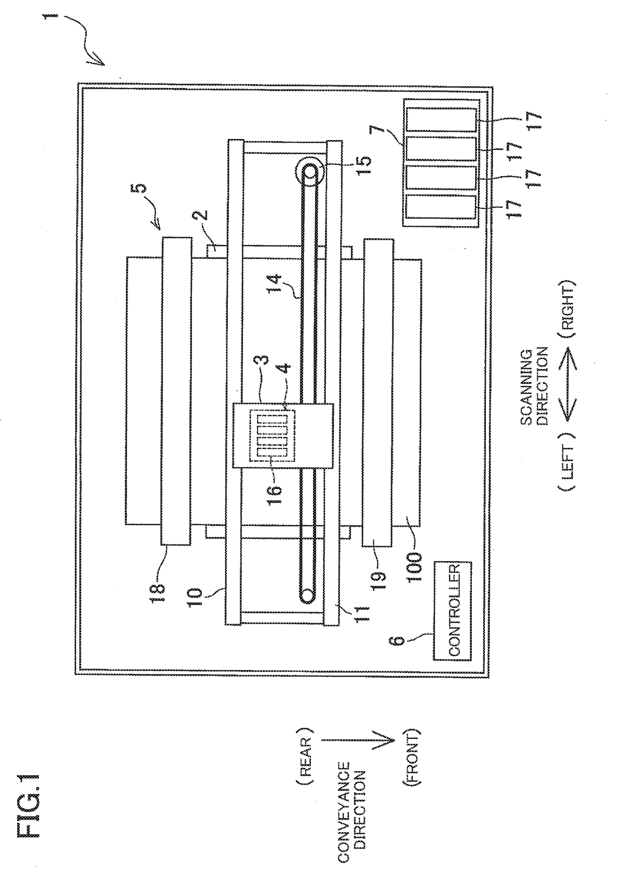
[0024]Referring first to FIG. 1, there will be explained a schematic structure of an ink-jet printer 1 according to a Directions respectively indicated as “front”, “rear”, “right”, and “left” in FIG. 1 are respectively defined as a front side, a rear side, a right side, and a left side of the printer 1. Further, one of opposite sides of the sheet of FIG. 1 corresponding to the front surface of the sheet is defined as an upper side of the printer 1 while the other side corresponding to the back surface of the sheet is defined as a lower side of the printer 1. The following explanation is based on these definitions.

Overall Structure of Printer

[0025]As shown in FIG. 1, the ink-jet printer 1 includes a platen 2, a carriage 3, an ink-jet head 4, a conveyor mechanism 5, and a controller 6.

[0026]A recording sheet 100, as one example of a recording medium, is placed on the platen 2. The carriage 3 is movable in a region in which the carriage 3 is opposed to the platen 2, so as to reciproca...

second embodiment

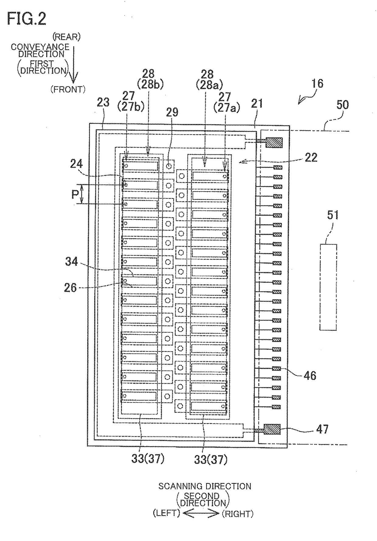
[0077]In the second embodiment, however, the contact holes 55 and the connecting members 56 for connecting the common wiring 44 and the common electrode 32 are located in the intermediate region between the two pressure-chamber rows 28. That is, the connecting member 56 is located close to the annular conductor 85 that is located at a position overlapping the inner end portion of the pressure chamber 26. In this instance, if the second conductive portion 44b of the common wiring 44 connected to the connecting member 56 is disposed so as to bypass the annular conductor 85, it may take up additional space depending upon the layout. To avoid such inconvenience, the annular conductor 85 is connected to the second conductive portion 44b for space saving.

[0078]FIGS. 11A and 11B are partly enlarged plan views of head units according to modifications. Also in a configuration shown in FIG. 11A in which the contact hole 55 and the connecting member 56 are disposed in a region overlapping the ...


PUM


Abstract

A liquid ejecting device, including: a flow-path defining member having a pressure chamber formed therein; a piezoelectric actuator constituted by a plurality of layers which includes a piezoelectric layer, a common electrode, and an individual electrode, superposed on the flow-path defining member, and having a through-hole communicating with the pressure chamber; an annular conductor disposed on one of opposite surfaces of the piezoelectric actuator remote from the flow-path defining member such that a part of the layers are sandwiched between the annular conductor and the common electrode, the annular conductor surrounding a periphery of the through-hole; and a liquid supply member having a supply path communicating with the through-hole and bonded to the one of the opposite surfaces via the annular conductor, wherein the annular conductor is connected to a terminal configured to be given a predetermined constant potential and is exposed to a flow path defined by the through-hole.

Description

CROSS REFERENCE TO RELATED APPLICATION[0001]The present application claims priority from Japanese Patent Application No. 2015-189283, which was filed on Sep. 28, 2015, the disclosure of which is herein incorporated by reference in its entirety.BACKGROUND[0002]Technical Field[0003]The disclosure relates to a liquid ejecting device.[0004]Description of Related Art[0005]An ink-jet head configured to eject ink from nozzles is known as one example of a liquid ejecting device. The known ink-jet head includes a flow-path defining plate in which a plurality of pressure chambers are formed, a piezoelectric actuator provided on the flow-path defining plate so as to cover the pressure chambers, and a reservoir defining plate bonded to an upper surface of the piezoelectric actuator.[0006]The flow-path defining plate is provided with a manifold (communication portion) extending in a direction in which the pressure chambers are arranged. The manifold is open to an upper surface of the flow-path d...

Claims


Application Information

Patent Timeline
IPC IPC(8): B41J2/14
CPCB41J2002/14491B41J2/14209B41J2/04581B41J2/14233B41J2002/14241B41J2202/18
Inventor KOIDE, SHOHEIHIRAI, KEITA
Owner BROTHER KOGYO KK
Why Eureka
Try Eureka