Hierarchical continuous level of detail for three-dimentional meshes

a three-dimensional mesh and detail layer technology, applied in the field of graphic processing, can solve the problems of large amount of computing resources involved in rendering, substantially to the number of primitives involved, and complex rendered scenes, and achieve the effect of simplifying the parent mesh accounting for inherited splitting planes and reducing visual artifacts

Inactive Publication Date: 2017-03-30
ROGERS DOUGLAS
View PDF0 Cites 18 Cited by
  • Summary
  • Abstract
  • Description
  • Claims
  • Application Information

AI Technical Summary

Benefits of technology

[0005]Among other things, systems and methods are described herein for using hierarchical continuous level of detail (H-CLOD) trees with inherited splitting plane partitioning to reduce visual artifacts in continuous level of detail renderings. Embodiments operate in context of three-dimensional meshes that model objects as coordinate points connected by edges (line segments) to define faces. A mesh can be iteratively split by, in each iteration, defining a splitting plane that partitions the mesh into two or more sub-meshes, until each sub-mesh is smaller than a predetermined mesh size (referred to herein as “bucket size”). The splitting can be assigned to a hierarchical tree, such that the original mesh is the root node, each sub-mesh is a child node to the mesh from which it was generated by splitting. The smallest meshes are leaf nodes, which can each contain no more than the bucket size number of faces. An H-CLOD tree can be generated by simplifying and combining each group of sibling node sub-meshes, by a bottom-up traversal of the tree, into a simplified parent mesh accounting for inherited splitting planes. The simplified parent meshes can replace the previously un-simplified parent meshes in the tree, so that the resulting H-CLOD tree has a most simplified mesh as its root node and a most un-simplified mesh formed by a combination of its leaf nodes.

Problems solved by technology

Further, rendered scenes are becoming more complex, for example, with larger numbers of complex objects in each scene, which can further add substantially to the number of primitives involved in rendering and displaying the scene.
As such, extremely large amounts of computing resources can be involved in rendering, particularly in real-time three-dimensional environments, such as video games, virtual immersive environments, etc.
However, changing of mesh complexities between renderings (e.g., between frames), can often manifest certain visual artifacts, such as popping.

Method used


Image

  • Hierarchical continuous level of detail for three-dimentional meshes
  • Hierarchical continuous level of detail for three-dimentional meshes
  • Hierarchical continuous level of detail for three-dimentional meshes

Examples


Embodiment Construction

[0033]In the following description, numerous specific details are set forth to provide a thorough understanding of various embodiments. However, one having ordinary skill in the art should recognize that the invention can be practiced without these specific details. In some instances, circuits, structures, and techniques have not been shown in detail to avoid obscuring embodiments.

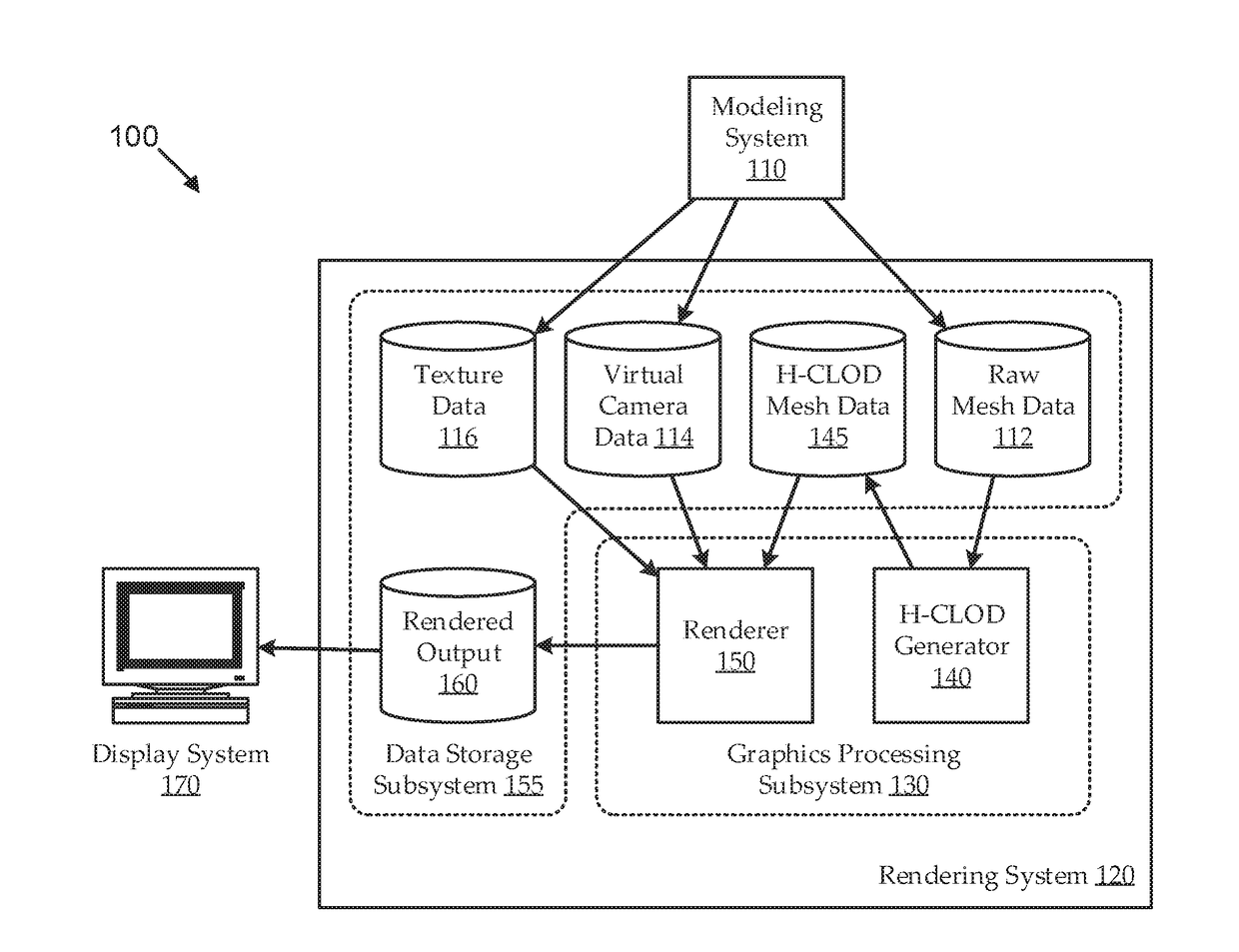
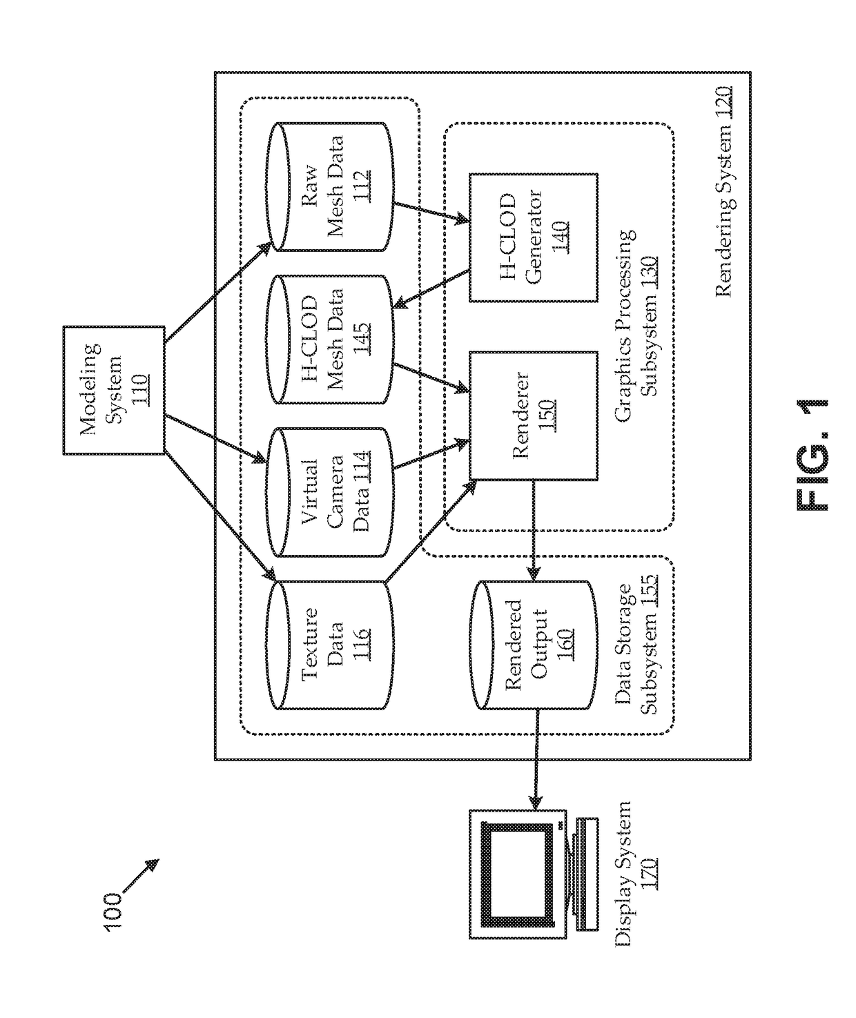
[0034]In three-dimensional computer graphics environments, objects in a scene are typically modeled as three-dimensional meshes made up of primitives (e.g., triangles or other polygons into coordinate points connected by edges). Rendering and displaying a three-dimensional object can often involve large numbers of computations to determine locations of, and complex interactions with, those coordinate points and edges, and the faces formed therefrom. Various techniques can be used to reduce the complexity of the meshes, thereby reducing the computational intensity involved in rendering and displaying the ob...


PUM


Abstract

Embodiments use hierarchical continuous level of detail (H-CLOD) trees with inherited splitting plane partitioning to reduce visual artifacts in renderings. For example, a three-dimensional mesh can be iteratively split, according to iteratively defined splitting planes, until sub-meshes are smaller than a predetermined bucket size. Each splitting can define a hierarchical level of a tree, so that the original mesh is a root node, each split sub-mesh is a child node, and the smallest meshes are leaf nodes. An H-CLOD tree can be generated by simplifying and combining each group of sibling node sub-meshes bottom-up into a simplified parent mesh accounting for inherited splitting planes, so that the tree has a most simplified mesh as its root node and a most un-simplified mesh formed by a combination of its leaf nodes. At render time, traversing the H-CLOD tree can produce a desired level of detail from the pre-computed nodes.

Description

FIELD[0001]Embodiments relate generally to graphics processing, and, more particularly, to generating and exploiting hierarchical levels of mesh detail that utilize inherited partitioning split planes to provide a continuous level of detail in arbitrary and other types of meshes.BACKGROUND[0002]In three-dimensional computer graphics environments, objects in a scene are typically modeled as three-dimensional meshes made up of primitives (e.g., triangles or other polygons resulting from decomposing of a surface by tessellation, or the like). The polygons can define faces of surfaces, and those surfaces can represent objects that are relatively simple, such as a flat wall; or objects that are relatively complex, such as a human or animal character. Surface maps (e.g., textures and / or skins) can be applied to the faces to produce a desired surface appearance of the object (e.g., color, texture, reflectivity, opacity, etc.). A three-dimensional scene can then be displayed by rendering th...

Claims


Application Information

Patent Timeline
Patent Type & Authority Applications(United States)
IPC IPC(8): G06T17/00G06T17/20
CPCG06T17/20G06T17/005
Inventor ROGERS, DOUGLAS
Owner ROGERS DOUGLAS
Why Eureka
Try Eureka