Wireless inductive power transfer

a technology of inductive power transfer and wireless, which is applied in the direction of transmission, electrical equipment, circuit arrangements, etc., can solve the problems of inconvenient use, impracticality, and battery use, and achieve the effect of increasing the difference between load changes and the detection of standby mode exit requests

Active Publication Date: 2017-03-30
KONINKLJIJKE PHILIPS NV
View PDF8 Cites 44 Cited by
  • Summary
  • Abstract
  • Description
  • Claims
  • Application Information

AI Technical Summary

Benefits of technology

[0085]This may allow improved detection of the standby mode exit request.
[0086]In particular, if the load change detection is based on excitations that occur s...

Problems solved by technology

However, this tends to be impractical and requires the user to physically insert connectors or otherwise establish a physical electrical contact.
It also tends to be inconvenient to the user by introducing lengths of wire.
Although, the use of internal batteries may avoid the need for a wired connection to a power supply during use, this only provides a partial solution as the batteries will need recharging (or replacing which is expensive).
The use of batteries may also add substantially to the weight and potentially cost and size of the devices.
The development of the Qi standard to cover an increasing variety of devices and applications also results in a number of new usag...

Method used


Image

  • Wireless inductive power transfer
  • Wireless inductive power transfer
  • Wireless inductive power transfer

Examples


Embodiment Construction

[0120]The following description focuses on embodiments of the invention applicable to a wireless power transfer system utilizing a power transfer approach such as is known from the Qi specification. However, it will be appreciated that the invention is not limited to this application but may be applied to many other wireless power transfer systems.

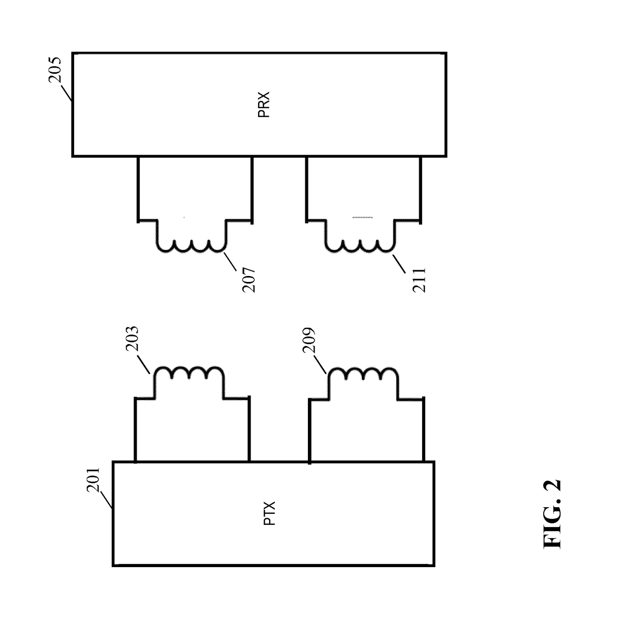
[0121]FIG. 2 illustrates an example of a power transfer system in accordance with some embodiments of the invention. The power transfer system comprises a power transmitter 201 which includes (or is coupled to) a transmitter power coil / inductor 203. The system further comprises a power receiver 205 which includes (or is coupled to) a receiver power coil / inductor 207.

[0122]The system provides a wireless inductive power transfer from the power transmitter 201 to the power receiver 205. Specifically, the power transmitter 201 generates a wireless power transfer signal (also for brevity referred to as a power signal or an inductive power signa...


PUM


Abstract

A wireless power transfer system includes a power transmitter (201) arranged to provide a power transfer to a power receiver (205) via a power transfer signal. The power receiver (205) comprises a first mode controller (709) for transmitting a standby mode exit request to the power transmitter (201) by changing a loading of a communication inductor (209) of the power transmitter (201). The power transmitter (201) comprises a mode controller (405) which controls the power transmitter (201) to operate in a standby mode wherein a presence of the power receiver (205) is detected but no power transfer signal is generated. It furthermore comprises a detector (403) for detecting an impedance change of the communication inductor (209). The mode controller (405) is arranged to initiate a transition from the standby mode to a power transfer mode in response to the detector (403) detecting the impedance change.

Description

FIELD OF THE INVENTION[0001]The invention relates to inductive power transfer and in particular, but not exclusively, to an inductive power transfer system in accordance with the Qi wireless power transfer standard.BACKGROUND OF THE INVENTION[0002]The number and variety of portable and mobile devices in use have exploded in the last decade. For example, the use of mobile phones, tablets, media players etc. has become ubiquitous. Such devices are generally powered by internal batteries and the typical use scenario often requires recharging of batteries or direct wired powering of the device from an external power supply.[0003]Most present day systems require a wiring and / or explicit electrical contacts to be powered from an external power supply. However, this tends to be impractical and requires the user to physically insert connectors or otherwise establish a physical electrical contact. It also tends to be inconvenient to the user by introducing lengths of wire. Typically, power r...

Claims


Application Information

Patent Timeline
IPC IPC(8): H02J50/12H04B5/00
CPCH04B5/0037H02J50/12H04B5/0075H04B5/0087H02J50/10H02J50/80H02J50/60H02J50/90
Inventor JOYE, NEIL FRANCISVAN WAGENINGEN, ANDRIESABERNETHY, SIMON GEORGELULOFS, KLAAS JACOB
Owner KONINKLJIJKE PHILIPS NV
Why Eureka
Try Eureka