
Aircraft propulsion system having at least one anti-fire tank

a propulsion system and anti-fire technology, applied in the direction of efficient propulsion technologies, machines/engines, engine starters, etc., can solve the problems of increasing the space available at the mast, and achieve the effect of greater holding capacity

Active Publication Date: 2017-04-06
AIRBUS OPERATIONS (SAS)
View PDF1 Cites 21 Cited by
  • Summary
  • Abstract
  • Description
  • Claims
  • Application Information

AI Technical Summary

Benefits of technology

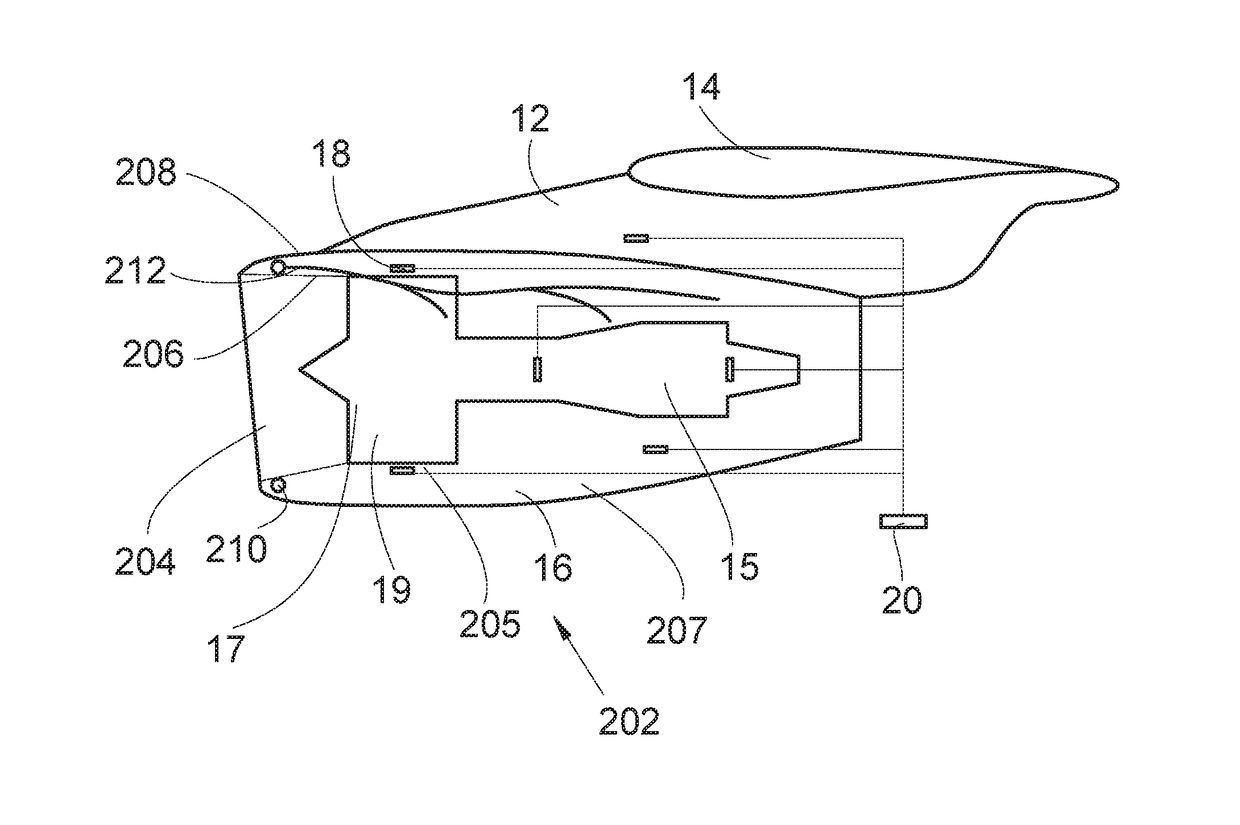
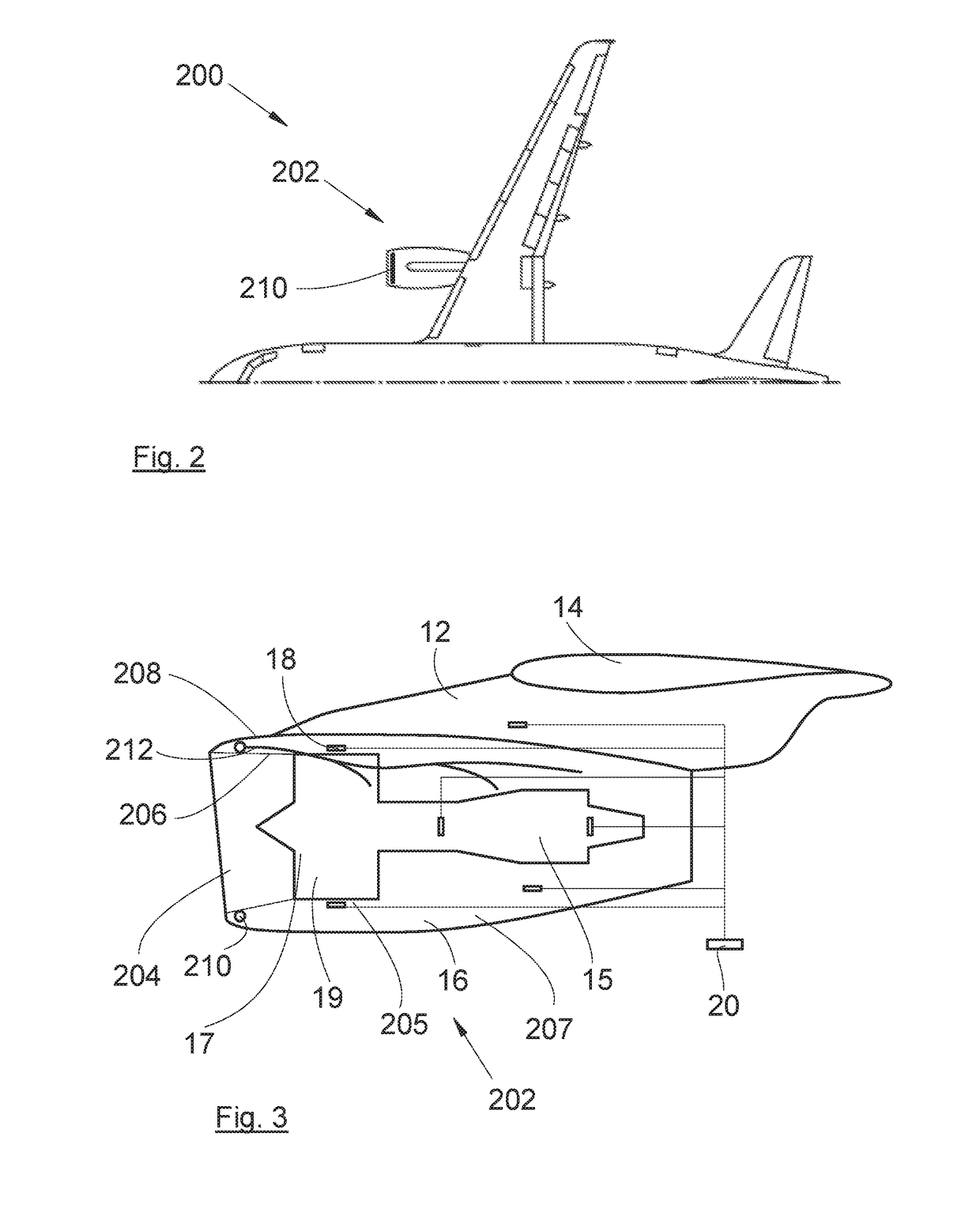
The present invention provides an aircraft propulsion system with an anti-fire tank that does not have the disadvantages of previous systems. The tanks have a greater holding capacity without taking up too much space at the mast. The system has a propulsion system with the tank or tanks placed in the nacelle, which allows for a larger volume of fluid to be carried and reduces the length of pipes and tanks needed. This results in a more efficient and effective system for protecting aircraft.

Problems solved by technology

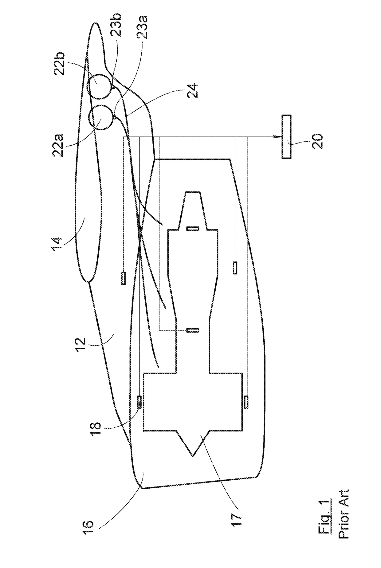
These new products require tanks that have greater holding capacities, and these increases are not always compatible with the space available at the mast, which is already a relatively crowded zone.

Method used


Image

  • Aircraft propulsion system having at least one anti-fire tank
  • Aircraft propulsion system having at least one anti-fire tank
  • Aircraft propulsion system having at least one anti-fire tank

Examples


first embodiment

[0053]In a first embodiment shown in FIG. 4, there are two tanks 410a-b, which are intended to be placed in the nacelle 16. Each tank 410a-b assumes the form of an open torus portion in a plane substantially perpendicular to the longitudinal axis of the nacelle 16 so as to adapt to the form of the nacelle 16, and is filled with an extinguishing fluid.

[0054]Each tank 410a-b is hydraulically connected to an evacuation pipe system 412 forming part of the network of pipes 212 and thus allowing the supply of extinguishing fluid to the network. In the embodiment of the invention presented here, the majority of the evacuation pipe system 412 is common to the two tanks 410a-b.

[0055]Between each tank 410a-b and the evacuation pipe system 412, there is arranged a valve 414a-b, for example of the explosive cartridge type, which, when activated by a pilot, allows the release of the extinguishing fluid from the associated tank 410a-b to the network of pipes 212.

[0056]In the embodiment of the in...

second embodiment

[0057]In the invention shown in FIG. 5, there are also two tanks 510a-b placed in the nacelle 16. Each tank 510a-b assumes the form of an open torus portion so as to adapt to the form of the nacelle 16 and is filled with an extinguishing fluid. Each tank 510a-b is hydraulically connected to an evacuation pipe system 512a-b forming part of the network of pipes 212 and thus allowing the supply of extinguishing fluid to the network. In the embodiment of the invention presented here, there is an evacuation pipe system 512a-b per tank 510a-b.

[0058]Between each tank 510a-b and the associated evacuation pipe system 512a-b there is arranged a valve 514a-b, for example of the explosive cartridge type, which, when activated by a pilot, allows the release of the extinguishing fluid from the associated tank 510a-b to the network of pipes 212.

[0059]In the embodiment of the invention of FIG. 5, each tank 510a-b extends angularly so that the lower part of each tank 510a-b is above a safety plane ...


PUM


Abstract

A propulsion system comprising a nacelle substantially tubular around a longitudinal axis, having an inner wall extending from a front to a rear of the nacelle and by an outer wall, external of the inner wall, extending from the front to the rear of the nacelle, a turbojet comprising a fan and situated internally of the inner wall of the nacelle, at least one tank containing an extinguishing fluid, and a network of pipes hydraulically connected to the tank. The propulsion system comprises each tank being located in the nacelle, around the inner wall and internally of the outer wall. Such a propulsion system makes it possible to shift the one or more tanks, which no longer occupy the space at the mast, and makes it possible to carry a large volume of extinguishing fluid so as to be able to accommodate future regulations.

Description

CROSS-REFERENCES TO RELATED APPLICATIONS[0001]This application claims the benefit of the French patent application No. 1559380 filed on Oct. 2, 2015, the entire disclosures of which are incorporated herein by way of reference.TECHNICAL FIELD[0002]The present invention relates to an aircraft propulsion system having at least one anti-fire tank, and to an aircraft having at least one such propulsion system.BACKGROUND OF THE INVENTION[0003]An aircraft conventionally has at least one propulsion system, comprising a nacelle inside which there is disposed an engine, for example of the turbojet type, and which is fixed to the structure of the aircraft by way of a mast fixed beneath the wing of the aircraft.[0004]In order to prevent damage to the structure of the aircraft when an engine catches fire, the aircraft conventionally has, for each nacelle, two tanks containing an extinguishing fluid, which can be a liquid or gaseous agent.[0005]FIG. 1 is a schematic illustration of a prior art pr...

Claims


Application Information

Patent Timeline
IPC IPC(8): B64D45/00B64D29/02F01D19/00B64D27/18F01D25/24F02K3/06
CPCB64D45/00F01D25/24F02K3/06B64D2045/009B64D27/18B64D29/02F05D2220/323F01D19/00B64C7/02F02C7/25F05D2250/71F05D2250/36Y02T50/60A62C3/08A62C35/023
Inventor PORTE, ALAINROGERO, JEAN MICHEL
Owner AIRBUS OPERATIONS (SAS)
Learn More