Aerosol sensor and sensing method

Active Publication Date: 2017-04-06
KONINKLJIJKE PHILIPS NV
View PDF1 Cites 9 Cited by
  • Summary
  • Abstract
  • Description
  • Claims
  • Application Information

AI Technical Summary

Benefits of technology

[0029]This enables the optical sensor to provide more accurate readings between the particle generating events, at which time more accurate particle mass information is obtained by the mechanical sens

Problems solved by technology

Especially in China, excessive PM2.5 pollution has become a common problem in the last decade.
However, continuous mass accumulation during the lifetime of the sensor is inevitable.
This problem is more pronounced for MEMS scale devices, in which mechanical and/or ch

Method used


Image

  • Aerosol sensor and sensing method
  • Aerosol sensor and sensing method
  • Aerosol sensor and sensing method

Examples


Embodiment Construction

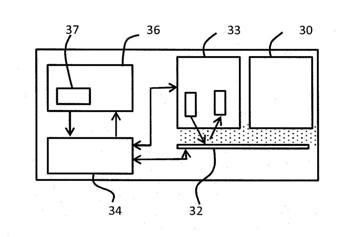
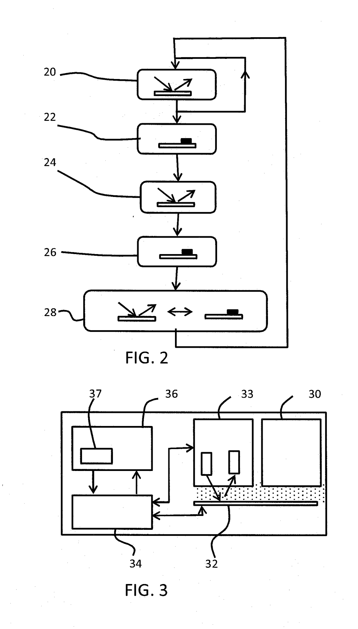
[0057]The invention provides a sensor system for measuring particle concentration and mass concentration in an aerosol. An optical sensor is used for measuring a particle concentration and optionally the size distribution, and a mechanical sensor is used for measuring a mass of collected particles. The particle concentration (and optionally size distribution) in the aerosol is monitored using the optical sensor until detection of a particle generating event. Upon detection of the particle generating event, a mass measurement using the mechanical sensor is performed and the mass measurement is used to calibrate the optical sensor. This approach enables the lifetime of the mechanical sensor to be extended, because it is only used when events are detected. The optical sensor, which typically is less accurate for mass concentration determination, is calibrated by the mechanical sensor.

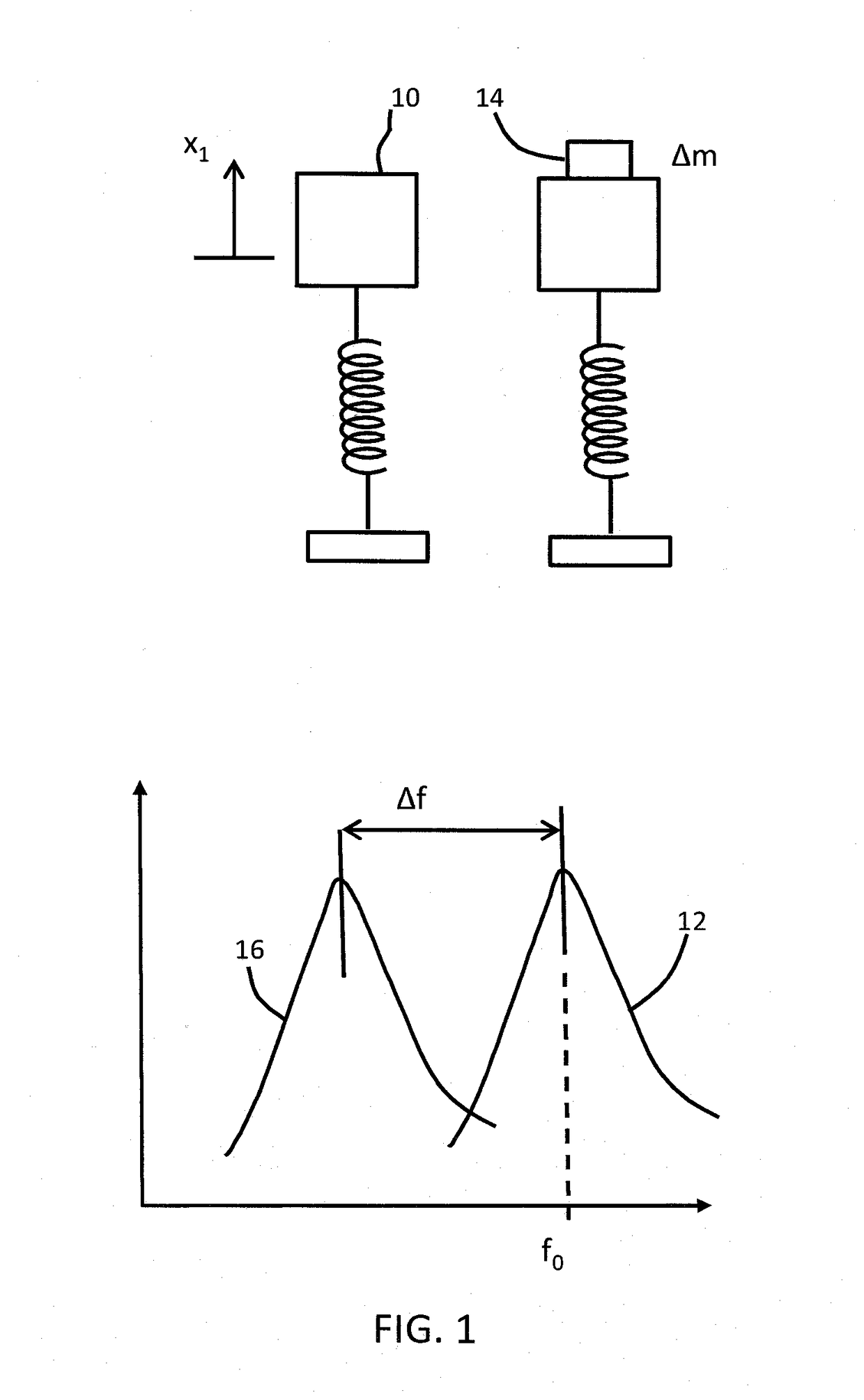
[0058]Direct mass measurement using resonant devices is a known technique. It is based on the relations...


PUM


Abstract

A sensor system is provided for measuring particle concentration and mass concentration in an aerosol. An optical sensor (33) is used for measuring a particle concentration and a mechanical sensor (32) is used for measuring a mass of collected particles. A particle concentration in the aerosol is monitored using the optical sensor (33), until detection of a particle generating event. Upon detection of a particle generating event, a mass measurement using the mechanical sensor (32) is performed and the mass measurement is used to calibrate the optical sensor (33). This approach enables the lifetime of the mechanical sensor to be extended, because it is only used when events are detected. The optical sensor, which typically is less accurate for mass sensing, is calibrated by the mechanical sensor.

Description

FIELD OF THE INVENTION[0001]The invention relates to the measuring of particle concentration and mass concentration within an aerosol.BACKGROUND OF THE INVENTION[0002]Airborne particle pollution, especially particle matter size less than 2.5 μm diameter range (named “PM2.5”), is a big concern for countries like China, where the speed of industrialization stretches the boundaries of regulatory requirements.[0003]As a consequence of increasing consumer empowerment, the demand for information about the air quality of living spaces is increasing. Especially in China, excessive PM2.5 pollution has become a common problem in the last decade. This problem is also validated by continuous measurements in various Chinese cities. The data is publicly available and can be simultaneously monitored by mobile phone applications or through the web.[0004]Availability of this data as well as continuous national and international media attention has created strong consumer awareness about the problem....

Claims


Application Information

Patent Timeline
IPC IPC(8): G01N15/06G01N29/12G01N15/02
CPCG01N15/06G01N15/0205G01N2291/028G01N2015/0693G01N2291/02408G01N29/12G01N29/022G01N29/036G01N5/02G01N21/532
Inventor KARAKAYA, KORAYKELLY, DECLAN PATRICK
Owner KONINKLJIJKE PHILIPS NV
Why Eureka
Try Eureka