Three-dimensional inspection of optical communication links

Inactive Publication Date: 2017-04-13
JOHN FLUKE MFG CO INC
View PDF12 Cites 9 Cited by
  • Summary
  • Abstract
  • Description
  • Claims
  • Application Information

AI Technical Summary

Benefits of technology

This patent is about a method and apparatus for inspecting the endface of a fiber optic cable using light to determine the presence and size of any defects. The apparatus includes a camera probe with two light sources that project light in different directions to create shadows caused by defects on the endface. The images obtained from the shadows are then compared to identify the defects and their dimensions. The technical effect is that this invention provides a non-destructive and efficient way to inspect fiber optic cables for quality control during manufacturing and installation processes.

Problems solved by technology

For instance, defects between optical fibers of two abutting fiber optic cables may block, diffuse, or misdirect the optical signal traveling from one optical fiber to another abutting optical fiber, thereby affecting the quality of the signal, such as reducing the intensity of the signal or introducing artifacts into the signal.
Furthermore, defects may cause damage to endfaces of optical fibers of another fiber optic cable upon coupling of the two fiber optic cables.

Method used


Image

  • Three-dimensional inspection of optical communication links
  • Three-dimensional inspection of optical communication links
  • Three-dimensional inspection of optical communication links

Examples


Embodiment Construction

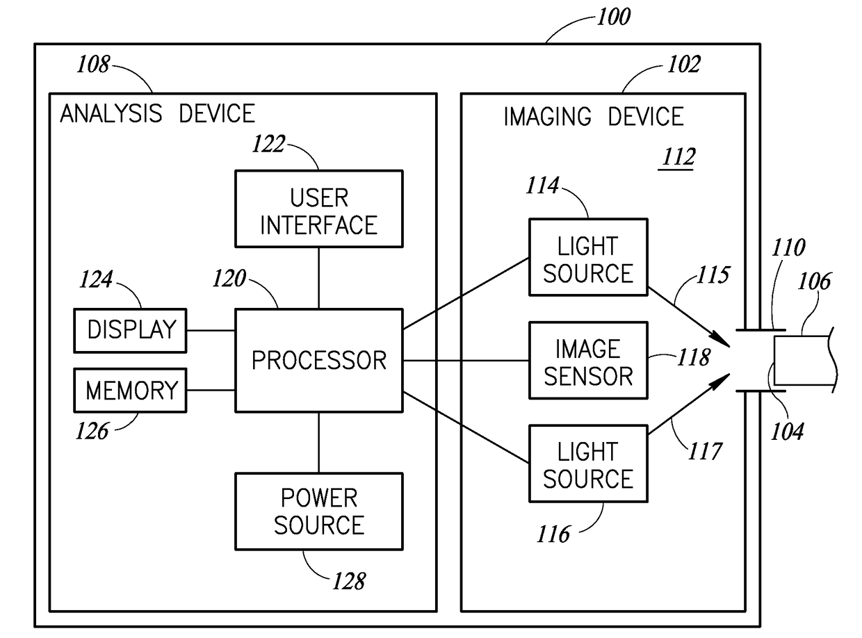
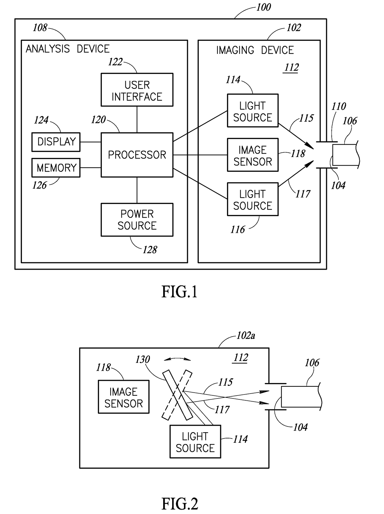
[0018]Embodiments are directed to apparatuses and methods for visually inspecting an endface of an optical communication link, such as a fiber optic cable. Generally described, the apparatus and methods include projecting light to an endface of an optical communication link in a first direction at a first angle of incidence and then projecting light to the endface in a second direction at a second angle of incidence.

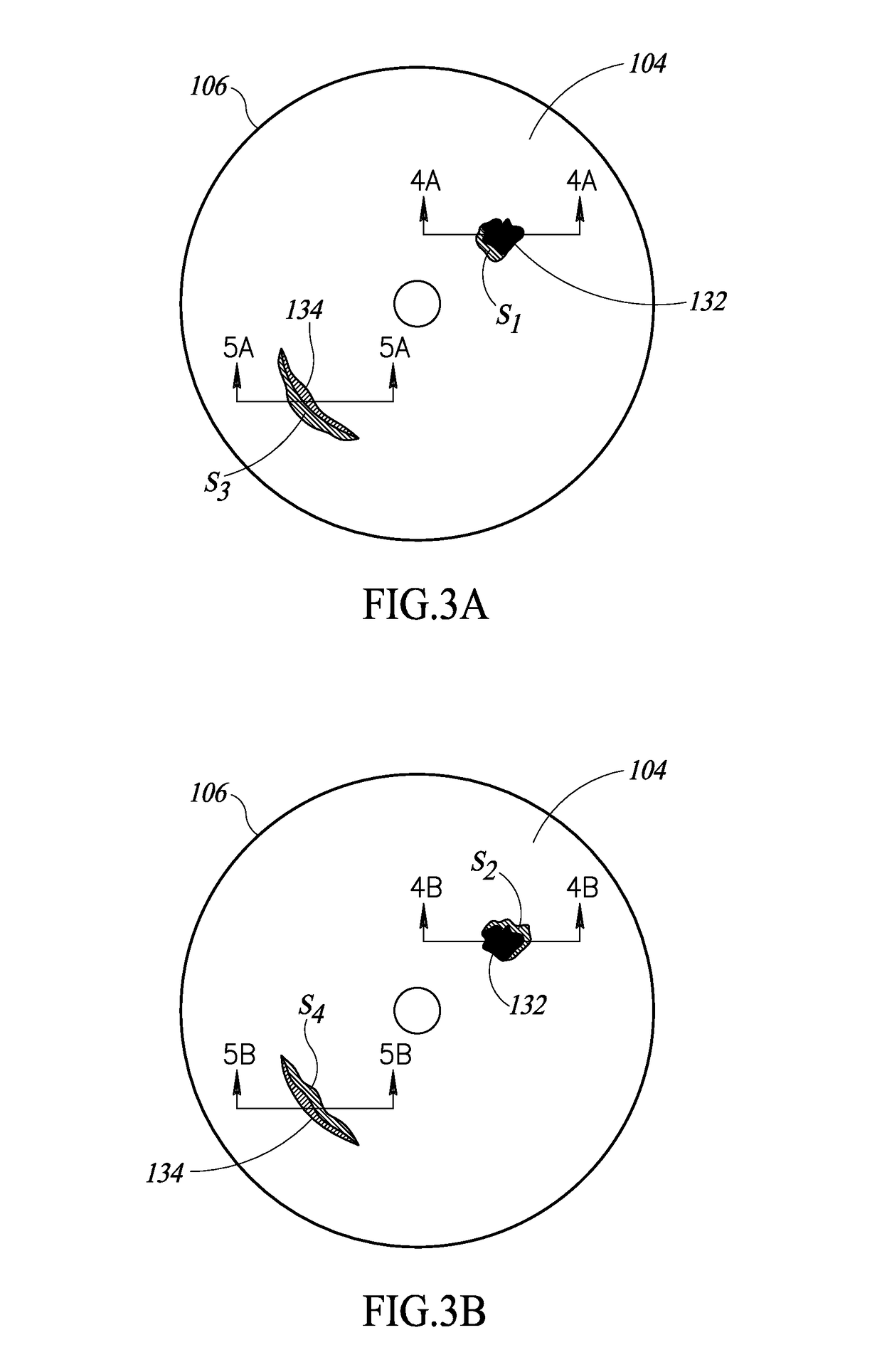
[0019]In various embodiments, the first and second angles of incidence typically are known angles that are less than normal. Defects on the endface will cast a first shadow when the light is projected in the first direction and a second shadow when the light is projected in the second direction. The shadows are then analyzed to determine whether the defect has a depth or a height. In particular, the shadows are analyzed to determine a length of at least one of the first and second shadows. Using the length of one of the first and second shadows and the known angle of inc...


PUM


Abstract

One or more embodiments are directed to camera probes and methods for visually inspecting an endface of an optical communication link, such as a fiber optic cable. Generally described, the camera probes and methods are directed to projecting light to an endface of the optical communication link from a first direction and at a first angle of incidence and projecting light to the endface at a second direction and at a second angle of incidence. A defect on the endface casts a first shadow when the light is projected in the first direction and a second shadow when the light is projected in the second direction. At least one of the first and second shadows is analyzed to determine its length. Using the length of the shadow and the known angle of incidence at which the light is projected, a height or depth of the defect is determined.

Description

BACKGROUND[0001]Technical Field[0002]The present disclosure generally pertains to visual inspections of optical communication links.[0003]Description of the Related Art[0004]Optical communication links, such as fiber optic cables, provide high speed transmission of data with relatively low loss. In view of this, optical communication links are often used in telecommunication networks, such as telephone lines, cable systems and the internet. In order to allow for adjustments to a network, such as adding, dropping, or moving optical cables in the network, or for coupling and decoupling to various transmitting and receiving equipment, each end of the fiber optic cables is held by a connector, such as a ceramic ferrule, a bulkhead adapter in a patch panel, etc., that allows for each of coupling and decoupling of the fiber optic cables. The connectors are designed to align the endfaces of the optical fibers of two fiber optic cables to be coupled, and to abut the endfaces of the optical ...

Claims


Application Information

Patent Timeline
IPC IPC(8): G01M11/00
CPCG01M11/31G01M11/30G01N21/94G01N21/95H04B10/0731G01B11/303G02B6/385G01B11/22G01N21/952G02B6/00
Inventor SCHELL, J. DAVIDKIM, WONOH
Owner JOHN FLUKE MFG CO INC
Why Eureka
Try Eureka