Rotary cutting tool including polycrystalline diamond material
a technology of diamond material and rotary cutting tool, which is applied in the direction of twist drills, manufacturing tools, transportation and packaging, etc., can solve the problems of drill reaches the end of their tool life early and the drill wear is generated, and achieves the effect of sufficient fracturing resistance of the pcd layer and stable cutting
- Summary
- Abstract
- Description
- Claims
- Application Information
AI Technical Summary
Benefits of technology
Problems solved by technology
Method used
Image
Examples
example 1
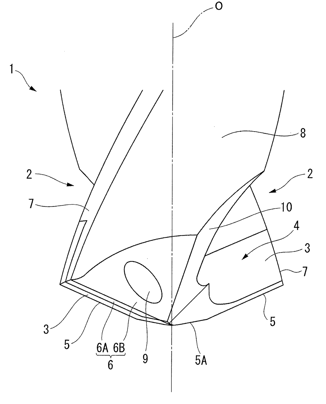
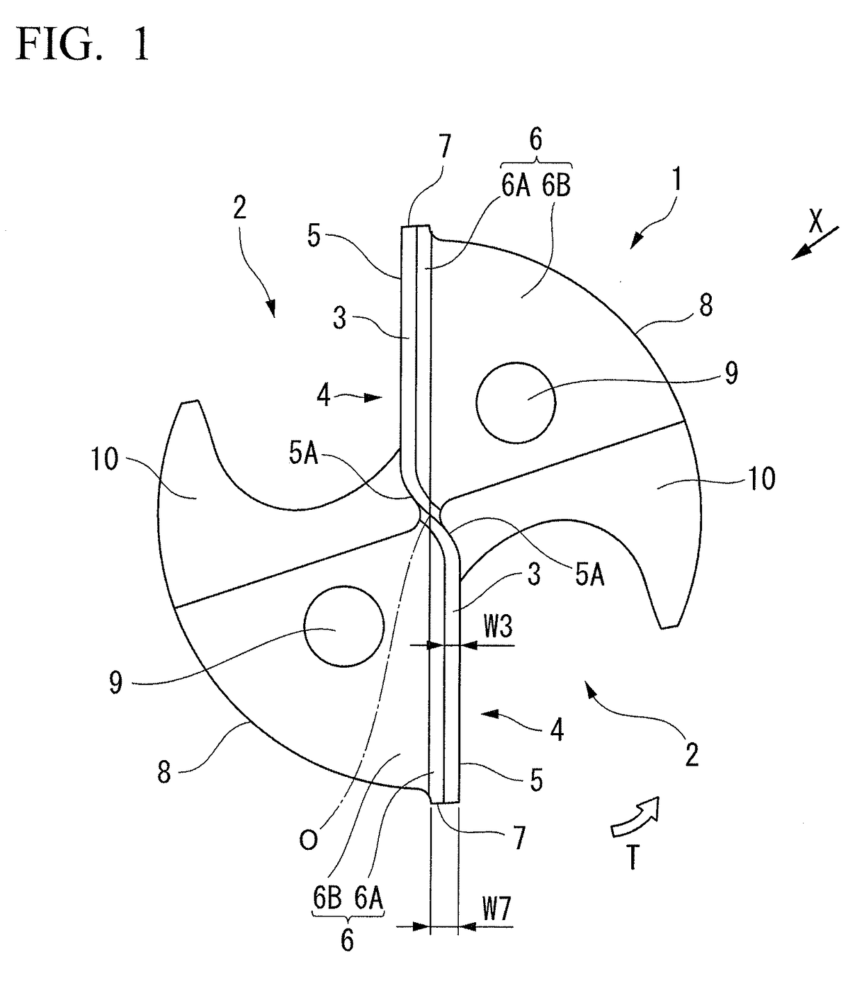
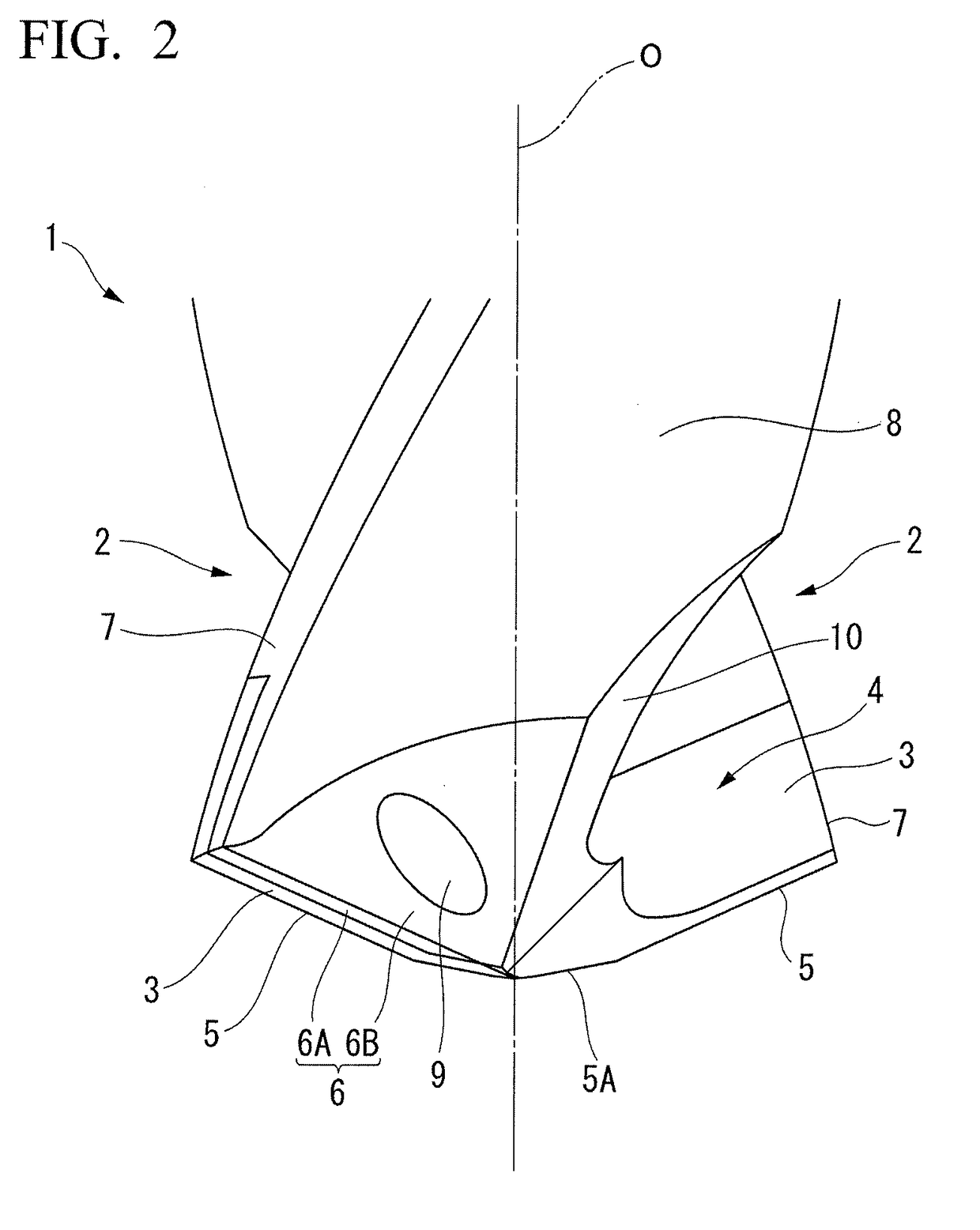
[0049]In Example 1, double-edge twist drills, each of which includes cutting edges 5 including linear outer peripheral portions and formed at ridge portions of the rake faces 4 at a tip side of the tool body 1, were produced on the basis of the above-mentioned first embodiment. A plurality of the double-edge twist drills were produced to satisfy conditions where the thickness W3 (i.e., the thickness of the PCD layer 3 exposed to the first flank 6A) was 1 / 3, 1 / 2 or 1 times the width W7 (i.e., the width of the margin portion 7, in this example, was 0.5 mm) Among these double-edge twist drills, by measurements using a microscope, three double-edge twist drills for each condition were selected where the thickness W3 of the PCD layer 3 was in the range of 1 / 3 to 1 times the width W7 of the margin portion 7 and a difference between the maximum value and the minimum value of the thickness W3 was set in the range equal to or smaller than 2 / 5 times the width W7 (equal to or smaller than 0.2 ...
example 2
[0055]Next, in Example 2, double-edge twist drills, each of which includes cutting edges 5 including outer peripheral portions having the shape of a concave curve and formed at ridge portions of rake faces 4 at a tip side of the tool body 1, were produced on the basis of the above-mentioned second embodiment. As in Example 1, three double-edge twist drills were produced to satisfy conditions where the thickness W3 (i.e., the thickness of the PCD layer 3 exposed to the first flank 6A) was 1 / 3, 1 / 2 or 1 times the width W7 (i.e., the width of the margin portion 7) and a difference between the maximum value and the minimum value of the thickness W3 was equal to or smaller than 2 / 5 times the width W7. These drills were referred to as Examples 2-1 to 2-9 as shown in Table 2. Further, three drills as Examples 2-10 to 2-12 were also produced where the thickness W3 of the PCD layer 3 was 1 / 2 times the width W7 of the margin portion 7 and a difference between the maximum value and the minimum...
example 3
[0059]In addition, in Example 3, three end mills, in each of which the present invention was applied to the above-mentioned end mill, were produced to satisfy conditions where the thickness W13 (i.e., the thickness of the PCD layer 13 exposed to the margin portion (the first outer peripheral flank face) in the circumferential direction) was 1 / 3, 1 / 2 or 1 times the width W17 (i.e., the width of the margin portion 17 in the circumferential direction) and a difference between the maximum value and the minimum value of the thickness W13 was equal to or smaller than 2 / 5 times the width W17. These end mills were referred to as Examples 3-1 to 3-9 as shown in Table 3. Further, three end mills as Examples 3-10 to 3-12 were also produced where the thickness W13 of the PCD layer 13 was 1 / 2 times the width W17 of the margin portion 17 and a difference between the maximum value and the minimum value of the thickness W13 of the PCD layer 13 was larger than 2 / 5 times the width W17. As Comparative...
PUM
| Property | Measurement | Unit |
|---|---|---|
| grain size | aaaaa | aaaaa |
| stress concentration | aaaaa | aaaaa |
| stress concentration | aaaaa | aaaaa |
Abstract
Description
Claims
Application Information
 - R&D
- Intellectual Property
- Life Sciences
- Materials
- Tech Scout
- Unparalleled Data Quality
- Higher Quality Content
- 60% Fewer Hallucinations
Browse by: Latest US Patents, China's latest patents, Technical Efficacy Thesaurus, Application Domain, Technology Topic, Popular Technical Reports.
© 2025 PatSnap. All rights reserved.Legal|Privacy policy|Modern Slavery Act Transparency Statement|Sitemap|About US| Contact US: help@patsnap.com


