Fluid pump

Active Publication Date: 2017-04-20
TBK
View PDF5 Cites 2 Cited by
  • Summary
  • Abstract
  • Description
  • Claims
  • Application Information

AI Technical Summary

Benefits of technology

The present invention is designed to prevent fluid from leaking outside of a fluid pump without adding extra parts or processes. This is achieved by using the attachment member of the electromagnetic clutch as a cover for sealing the opening of a fluid storage portion. This prevents water leakage in front of the fluid pump and reduces the number of parts and assembly processes, lowering manufacturing costs. Additionally, the fluid storage portion is designed as an annular space, efficiently securing a spatial volume and preventing dew condensation formation. Overall, the invention prevents fluid leakage more effectively.

Problems solved by technology

In such a fluid pump configured as described above, however, when the mechanical seal involves foreign matters such as dust, there is a possibility that a small amount of cooling water leaks from the mechanical seal.
This is structurally inevitable as long as a mechanical seal is employed as the sealing means, and if the leaked cooling water leaks from the fluid pump to the outside, there is a risk of misjudging that the fluid pump has broken down.
However, this configuration requires a special cover for removably sealing the opening of the water storage space, leading to an increase in the number of parts or mounting processes and thus the cost of manufacturing the fluid pump.

Method used


Image

  • Fluid pump
  • Fluid pump
  • Fluid pump

Examples


Embodiment Construction

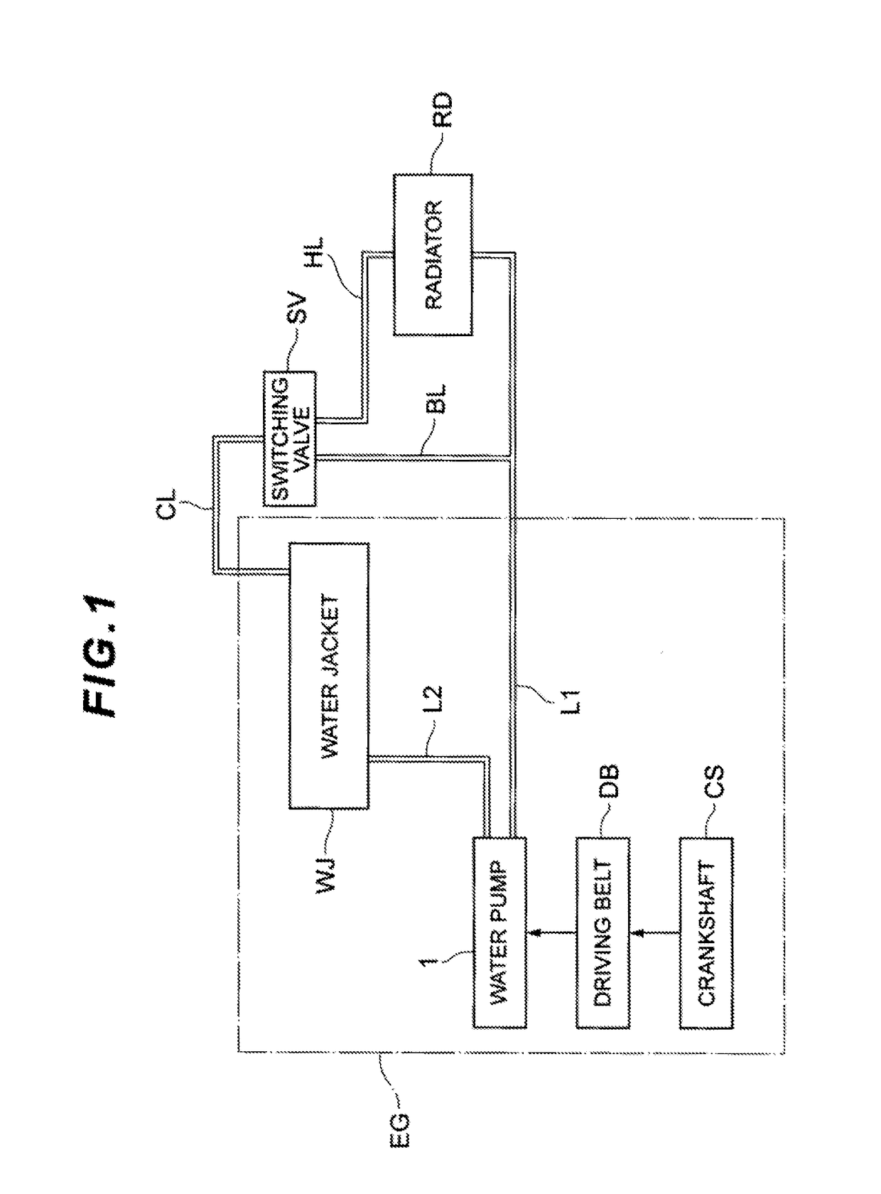
[0017]A preferred embodiment of the present invention is described hereinafter with reference to the drawings. A water pump (fluid pump) according to an embodiment of the present invention is provided on the inside of a cooling water circulation passage to forcibly circulate the cooling water. Before explaining the water pump of the present embodiment, this cooling water circulation passage is described first with reference to FIG. 1.

[0018]As shown in FIG. 1, an engine EG as a water-cooled internal combustion engine, a radiator RD for cooling the cooling water (a medium for cooling the engine) discharged from the engine EG, a switching valve SV for controlling the circulation of the cooling water in accordance with the temperature of the cooling water, and a water pump 1 for forcibly circulating the cooling water, are disposed on the inside of the cooling water circulation passage, wherein the engine EG is cooled by the circulation of the cooling water through a plurality of flow pa...


PUM


Abstract

The fluid pump according to the present invention has water storage means that is formed so as to communicate with a shaft hole in a pump case and stores fluid leaking from a mechanical seal. An electromagnetic clutch establishes or blocks the transmission of power to a drive shaft by switching between supply and non-supply of electricity to an excitation coil. The water storage means has a weep chamber that communicates with the shaft hole between the mechanical seal and a bearing and is opened to an end portion in the axial direction. An attachment member for attaching a core of the electromagnetic clutch to the pump case seals the opening of the weep chamber.

Description

RELATED APPLICATIONS[0001]This invention claims the benefit of Japanese Patent Application No. 2015-206616 which is hereby incorporated by reference.TECHNICAL FIELD[0002]The present invention relates to a fluid pump such as a water pump.TECHNICAL BACKGROUND[0003]Water-cooled engines such as automotive engines have conventionally been using water (cooling water) as a medium for cooling the cylinders and cylinder head and have a fluid pump as a device for forcibly circulating the cooling water by feeding the cooling water to a water jacket formed within the cylinder block of the engine. Such a fluid pump is typically called “water pump,” and has a pump base configured from a part of the cylinder block and having an inlet port and an outlet port for the cooling water, a pump case attached to the pump base and configuring a pump chamber, a pump pulley supported rotatably in an outer circumferential portion of the pump case, a drive shaft that has one end portion coupled to the pump pull...

Claims


Application Information

Patent Timeline
IPC IPC(8): F04D29/40F01P5/12F04D29/10F04D29/046F04D29/22F01P3/18F04D13/02
CPCF04D29/406F01P3/18F01P5/12F04D13/024F04D29/046F05B2260/603F04D29/106F05B2240/14F05B2240/30F05B2240/50F05B2240/57F04D29/22F04D13/02F05D2260/6022F05D2240/55F04D25/026F04D29/126
Inventor OSAWA, MAKOTO
Owner TBK
Why Eureka
Try Eureka