Device and method for relative positioning of multi-aperture optics comprising several optical channels in relation to an image sensor

Active Publication Date: 2017-04-20
FRAUNHOFER GESELLSCHAFT ZUR FOERDERUNG DER ANGEWANDTEN FORSCHUNG EV
View PDF2 Cites 16 Cited by
  • Summary
  • Abstract
  • Description
  • Claims
  • Application Information

AI Technical Summary

Benefits of technology

[0028]What is advantageous about this embodiment is that alignment of the multi-aperture optics in relation to the image sensor is enabled in six degrees of freedom about the inner image region on the basis of said focusing and centering of the image in relation to the inner image region, so that a high level of precision of the positioning is achieved.
[0029]In accordance with a further embodiment, the calculating device is configure

Problems solved by technology

As far as active alignment is concerned, conventional optimization algorithms will fail if the parameters of the objectives vary only slightly in relation to the positioning steps.
The latter applies, e.g., to objectives having large depths of focus (and, in particular, multi-aperture objectives comprised of microlens arrays) wherein a change in the z distance between the objective and the image sensor results in only slight changes in the image sharpness that in real cases are difficult to measure.
Thus, the established active assembly processes and machines are not suitable of aligning objectives which comprise no rotational symmetry about the z axis.
This value lies within the range of depths of focus, so that any existing active assembly techniques based on evaluating the image contrast do not allow sufficient accuracy in aligning the objective in relation to the image sensor when applied to multi-aperture im

Method used


Image

  • Device and method for relative positioning of multi-aperture optics comprising several optical channels in relation to an image sensor
  • Device and method for relative positioning of multi-aperture optics comprising several optical channels in relation to an image sensor
  • Device and method for relative positioning of multi-aperture optics comprising several optical channels in relation to an image sensor

Examples


Embodiment Construction

[0057]Before detailed explanations shall be given below regarding embodiments of the present invention by means of the drawings, it shall be noted that elements, objects and / or structures that are identical or have identical functions or identical actions are provided with identical reference numerals in the various figures, so that the descriptions of said elements presented in different embodiments are mutually exchangeable and / or mutually applicable.

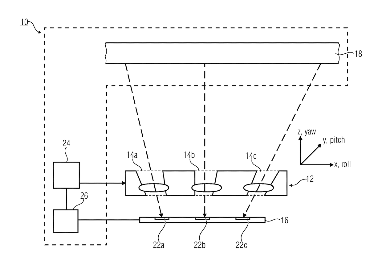
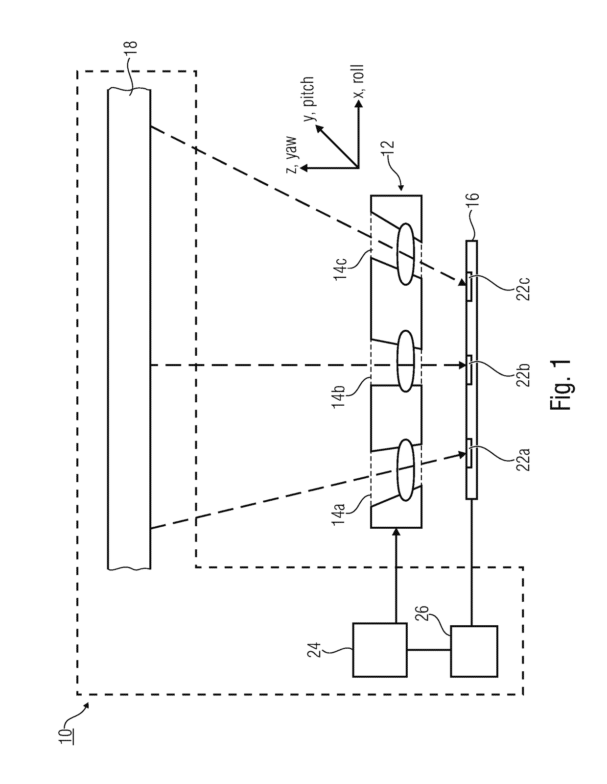
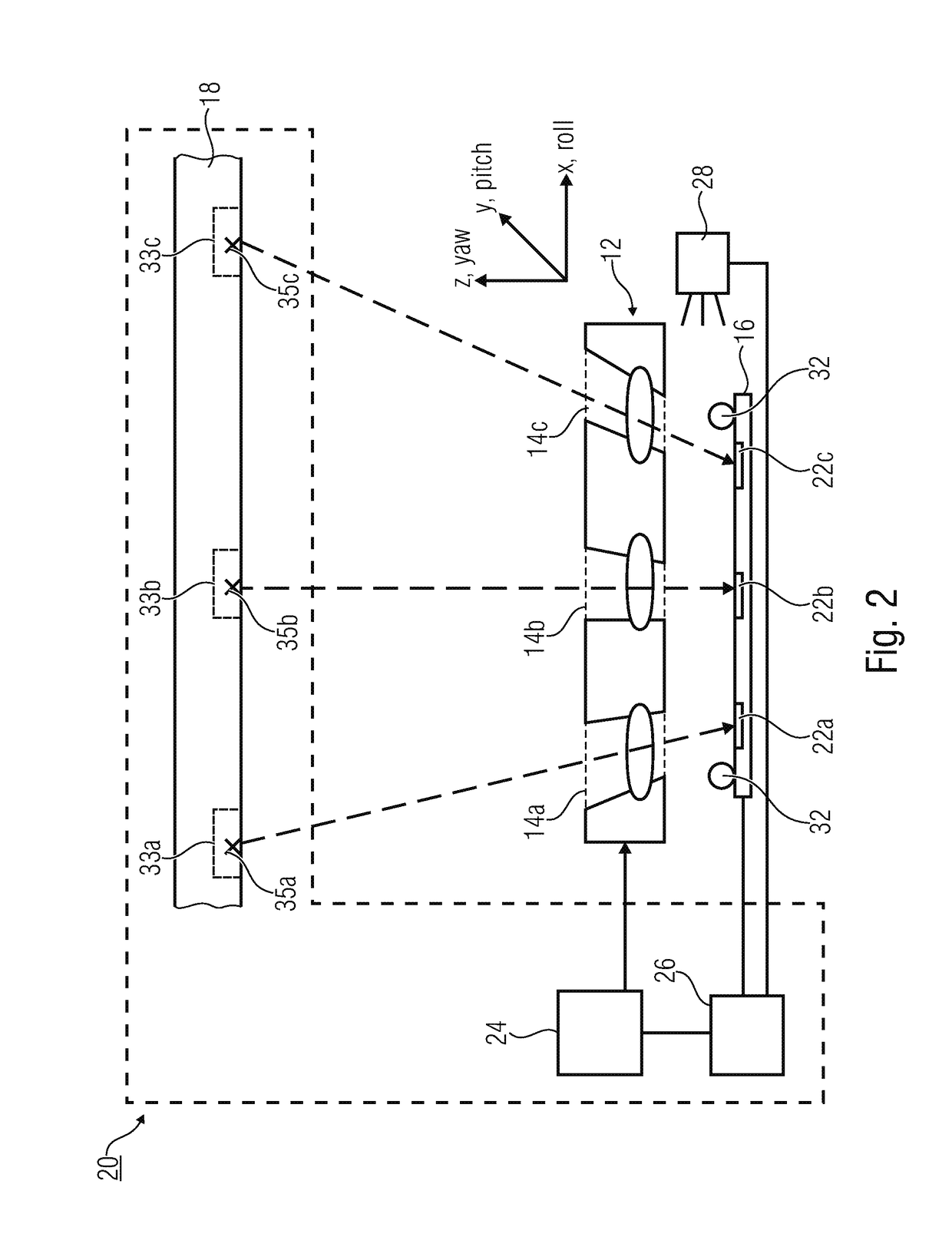
[0058]In the following, reference shall be made to the alignment of multi-aperture optics and an image sensor with several image regions, in relation to each other. Relative alignment may basically be performed in six degrees of freedom, which describe a translation along three spatial directions x,y, and z as well as a rotation about the x,y, and z axes. In addition, the following explanations relate to a roll axis, a pitch axis, and a yaw axis that are arranged, for simplified understanding, in parallel, or congruently with the x,y,...


PUM


Abstract

A device for relative positioning of multi-aperture optics having several optical channels in relation to an image sensor includes a reference object, a positioning device, and a calculating device. The reference object is arranged such that the reference object is imaged onto one image region per channel in the optical channels by the multi-aperture optics. The positioning device is controllable to change a relative location between the multi-aperture optics and the image sensor. The calculating device is configured to determine actual positions of the reference object in at least three image regions in images of the reference object and to control the positioning device on the basis of a comparison of the actual positions with positions.

Description

CROSS-REFERENCE TO RELATED APPLICATIONS[0001]This application is a continuation of copending International Application No. PCT / EP2015 / 064284, filed Jun. 24, 2015, which claims priority from German Application No. 10 2014 212 104.3, filed Jun. 24, 2014, which are each incorporated herein in its entirety by this reference thereto.[0002]The present invention relates to a device and a method for relative positioning of multi-aperture optics comprising several optical channels. The present invention further relates to a method for actively aligning multi-aperture optics with a digital image sensor.BACKGROUND OF THE INVENTION[0003]When manufacturing high-resolution miniaturized camera modules, the step of integrating an objective comprises performing an active alignment process, i.e. actively aligning the objective (object lens) in relation to the image sensor while observing and evaluating the image that arises. This involves moving the objective in relation to the image sensor and evalu...

Claims


Application Information

Patent Timeline
IPC IPC(8): H04N5/225H04N17/00G06T7/80
CPCH04N5/2254H04N5/2253G06T2207/30204H04N17/002G06T7/80H04N23/55H04N23/54
Inventor BRUECKNER, ANDREASWIPPERMANN, FRANKBRAEUER, ANDREAS
Owner FRAUNHOFER GESELLSCHAFT ZUR FOERDERUNG DER ANGEWANDTEN FORSCHUNG EV
Why Eureka
Try Eureka