
Blade design for cutting food and other items

Inactive Publication Date: 2017-04-27
SUTHAR YOGIN P
View PDF0 Cites 0 Cited by
  • Summary
  • Abstract
  • Description
  • Claims
  • Application Information

AI Technical Summary

Benefits of technology

The present invention is a cutting device with multiple parallel blade blades that have a non-linear or curved shape and different elevation in the cutting direction. This design allows for slicing into items with a reduction in force required, making it easier for users to start the process, and also extends the life of the device by minimizing the force repeatedly exerted on components. Additionally, this invention cuts from both sides, restraining the food item from moving during the cutting process.

Problems solved by technology

One practical shortcoming of this known device, and with similar food cutting devices, lies with the excessive amount of force necessary to press the food item through the grid of blades.
Not only does this excessive force make cutting difficult for the user, but it can exceed the mechanical limits of the hinged lid, which is often made of plastic, resulting in damage to the device.
However, such configurations do not maximize the utility of this concept; that is, the blades simultaneously make contact with the food at multiple points during the cutting process.
Additionally, existing cutting devices, using either a flat or modified grid of blades, do not function to control the position of the food item itself in a manner that prevents it from crushing or from slipping out of the device.
Existing blade designs do not provide this compression function as they cut.

Method used


Image

  • Blade design for cutting food and other items
  • Blade design for cutting food and other items
  • Blade design for cutting food and other items

Examples


Embodiment Construction

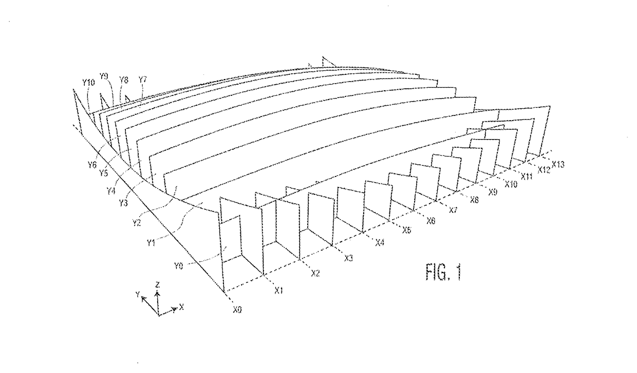
[0033]The preferred embodiments of the present invention will now be described with reference to FIGS. 1-8 of the drawings.

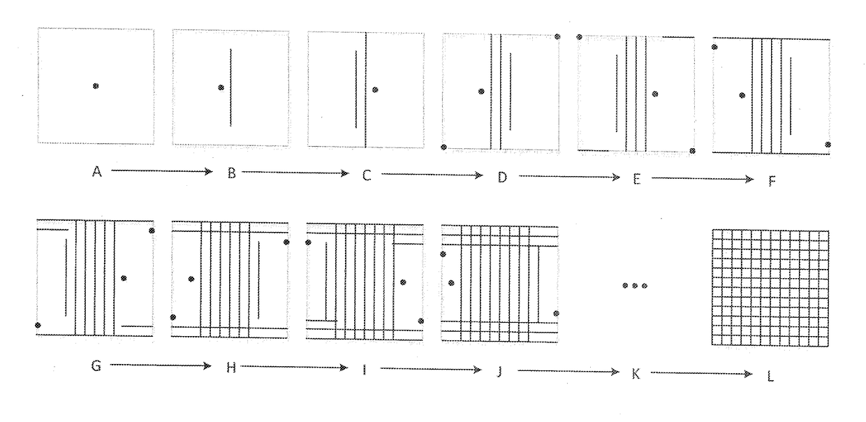
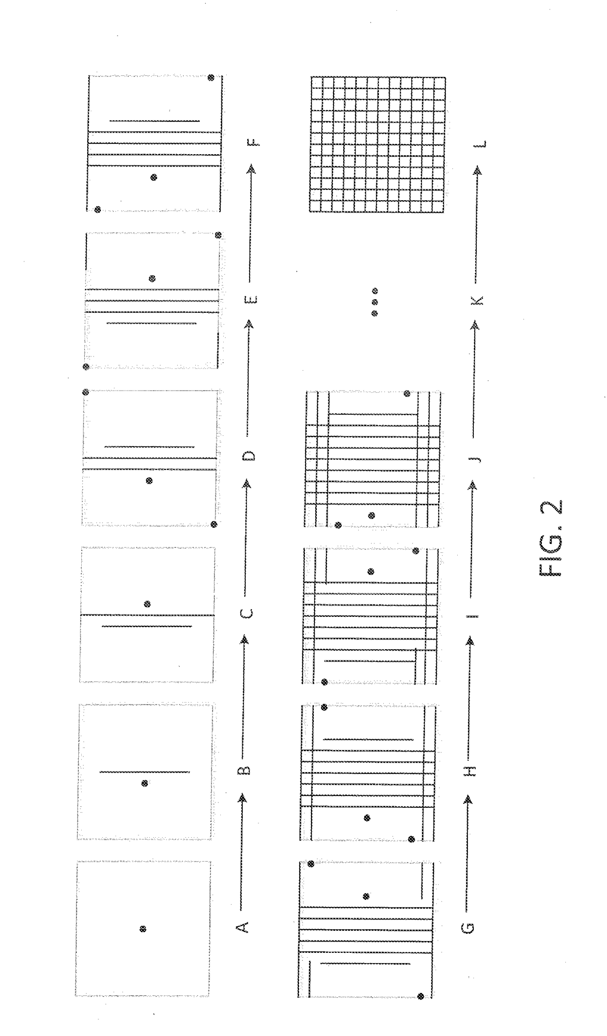
[0034]FIG. 1 shows a first preferred embodiment of the improved blade design according to the invention, in which there is a grid of non-flat blades along two axes. The blades on the Y axis, with labels Y0 through Y10, are convex with each blade having a peak point on the vertical Z axis. As may be seen, no two Y axis blades are at the same vertical elevation, each blade being slightly higher or lower than its neighboring Y axis blade. This is what allows the incremental penetration of the target item with minimum force, namely, that no two Y axis blades start to penetrate the food item at the same time. The Y axis blades are highest in the center and decrease in the Z axis as they move away from center. Each blade on the Y axis has a single peak point at or somewhat near in the center which commences the blade's penetration into the target item. The center Y ax...


PUM


Abstract

A cutting device for slicing or chopping food or the like has a plurality of parallel cutting blades, each with a leading cutting edge that is non-linear or even curved from one end to an opposite end thereof and is non-symmetric with respect to a central point between the ends. The leading cutting edge of each blade has a different elevation in the cutting direction than the leading cutting edges of the adjacent blades. With this arrangement the cutting edges of the various blades are caused to slice progressively into the sliceable object and thereby reduce the force required to create the parallel cuts through the object.

Description

BACKGROUND OF THE INVENTION[0001]The present invention relates to a cutting device for slicing or chopping a sliceable object such as food or the like. More particularly, the present invention concerns the blade design for cutting device of this type.[0002]In the process of food preparation it is often necessary to slice or chop food into small pieces. This type of cutting is not limited to food and may also apply to non-food items that have a similar consistency. A number of devices exist for this purpose. A popular food chopper is disclosed in the Kaposi U.S. Pat. No. 7,762,169. Kaposi provides a flat grid of blades and a hinged lid for pressing food downward against the blades. A food reservoir is arranged beneath the blades to catch the chopped food parts. One practical shortcoming of this known device, and with similar food cutting devices, lies with the excessive amount of force necessary to press the food item through the grid of blades. Not only does this excessive force mak...

Claims


Application Information

Patent Timeline
IPC IPC(8): B26B3/04B26D3/18
CPCB26D3/185B26B3/04
Inventor SUTHAR, YOGIN P.
Owner SUTHAR YOGIN P
Features
  • Generate Ideas
  • Intellectual Property
  • Life Sciences
  • Materials
  • Tech Scout
  • Unparalleled Data Quality
  • Higher Quality Content
  • 60% Fewer Hallucinations
Learn More