Rear-end diffuser arrangement for a motor vehicle

a rear-end diffuser and motor vehicle technology, applied in vehicle bodies, road transportation emission reduction, aerodynamic improvement, etc., can solve the problems of high cumbersome installation and integration of the rear-end diffuser arrangement in the underbody region, and achieve the effect of increasing the flexibility of the rear-end diffuser arrangemen

Active Publication Date: 2017-04-27
DR ING H C F PORSCHE AG
View PDF2 Cites 12 Cited by
  • Summary
  • Abstract
  • Description
  • Claims
  • Application Information

AI Technical Summary

Benefits of technology

[0011]Two or more flaps can be provided, thereby further increasing the flexibility of the rear-end diffuser arrangement with regard to fitting and design. At least one frame part for the flap may be provided in the rear-end arrangement. The

Problems solved by technology

The rear-end diffuser arrangement disclosed in DE 10 2013 105 842 A1 is highly

Method used


Image

  • Rear-end diffuser arrangement for a motor vehicle
  • Rear-end diffuser arrangement for a motor vehicle
  • Rear-end diffuser arrangement for a motor vehicle

Examples


Embodiment Construction

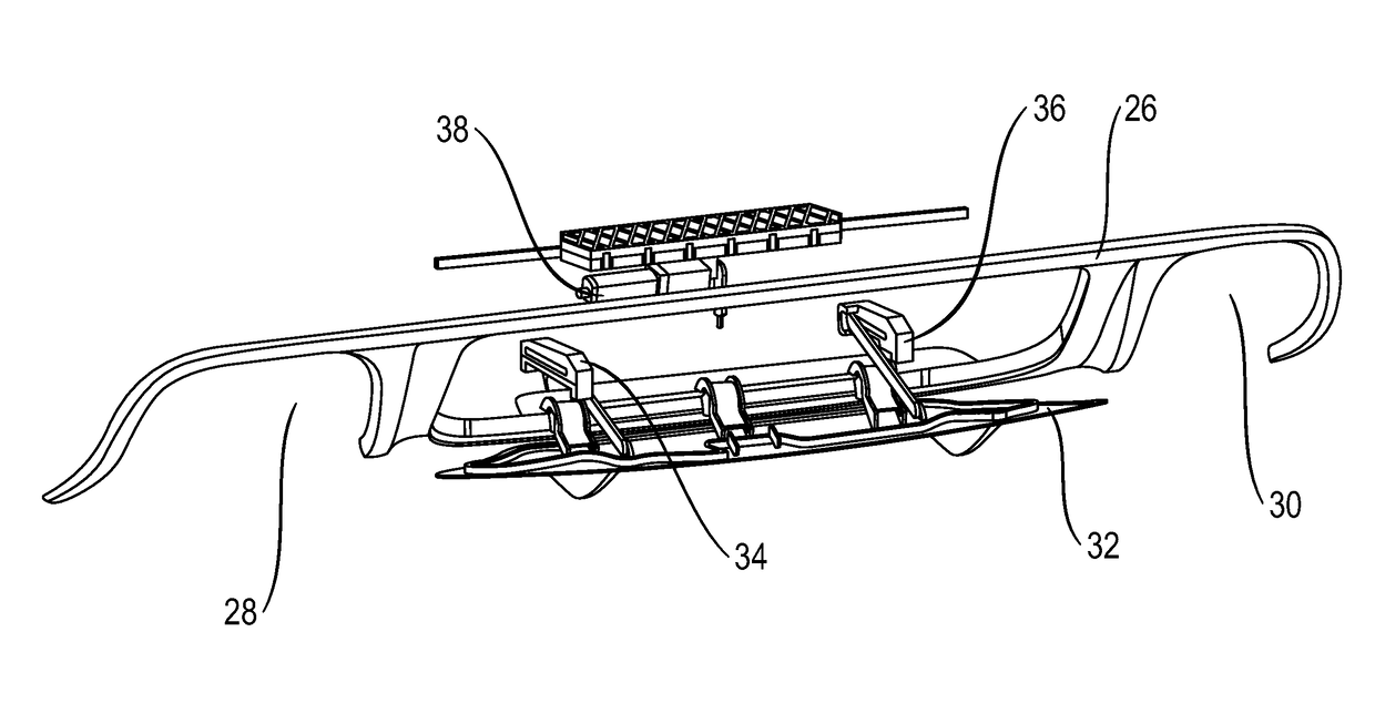
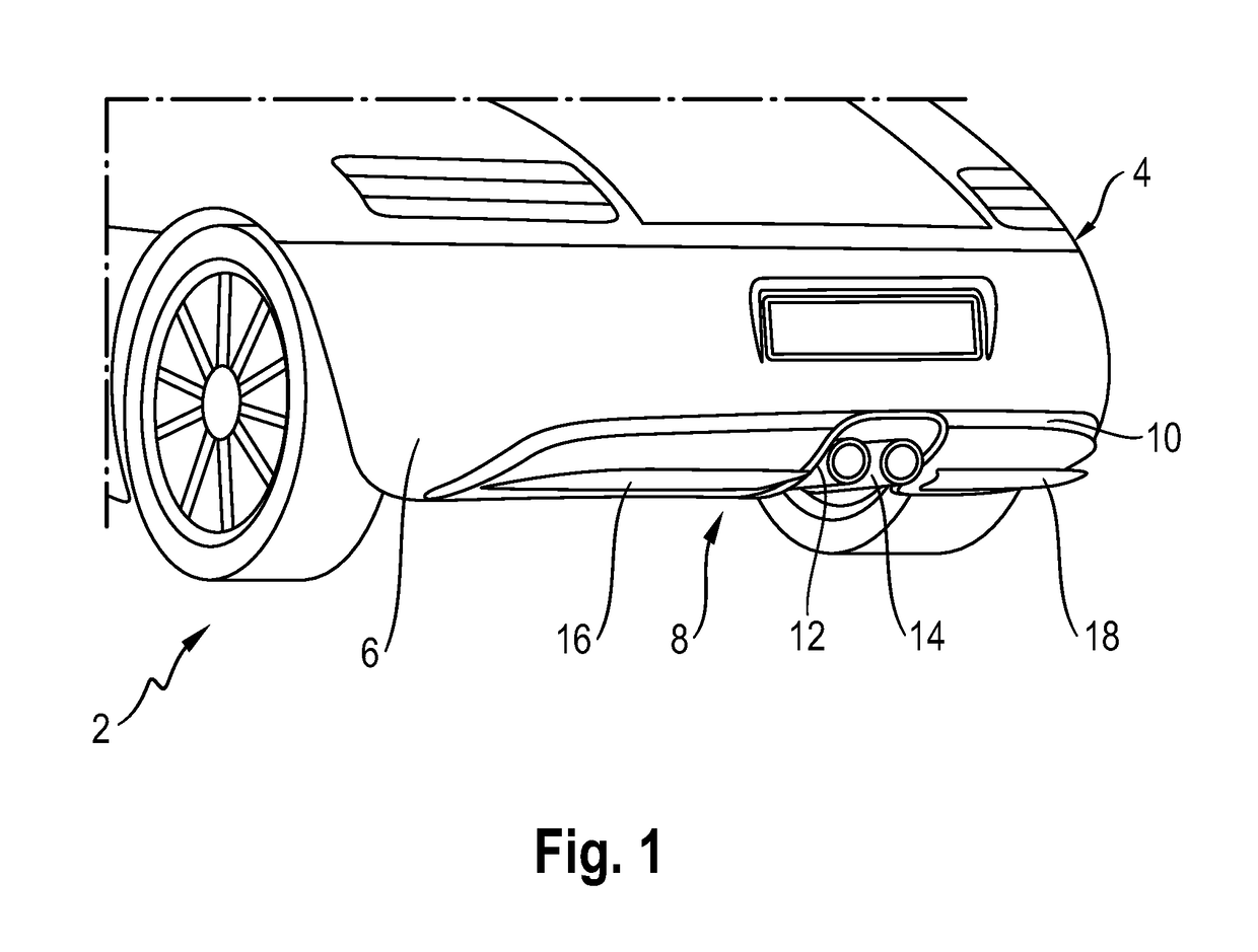
[0015]FIG. 1 illustrates a motor vehicle 2 having a rear-end arrangement 4 with a bumper element 6 and a rear-end diffuser arrangement 8. The rear-end diffuser arrangement 8 has a frame part 10 with a cutout 12 for a twin exhaust tailpipe 14 and two flaps 16, 18 are mounted movably on the frame part 10.

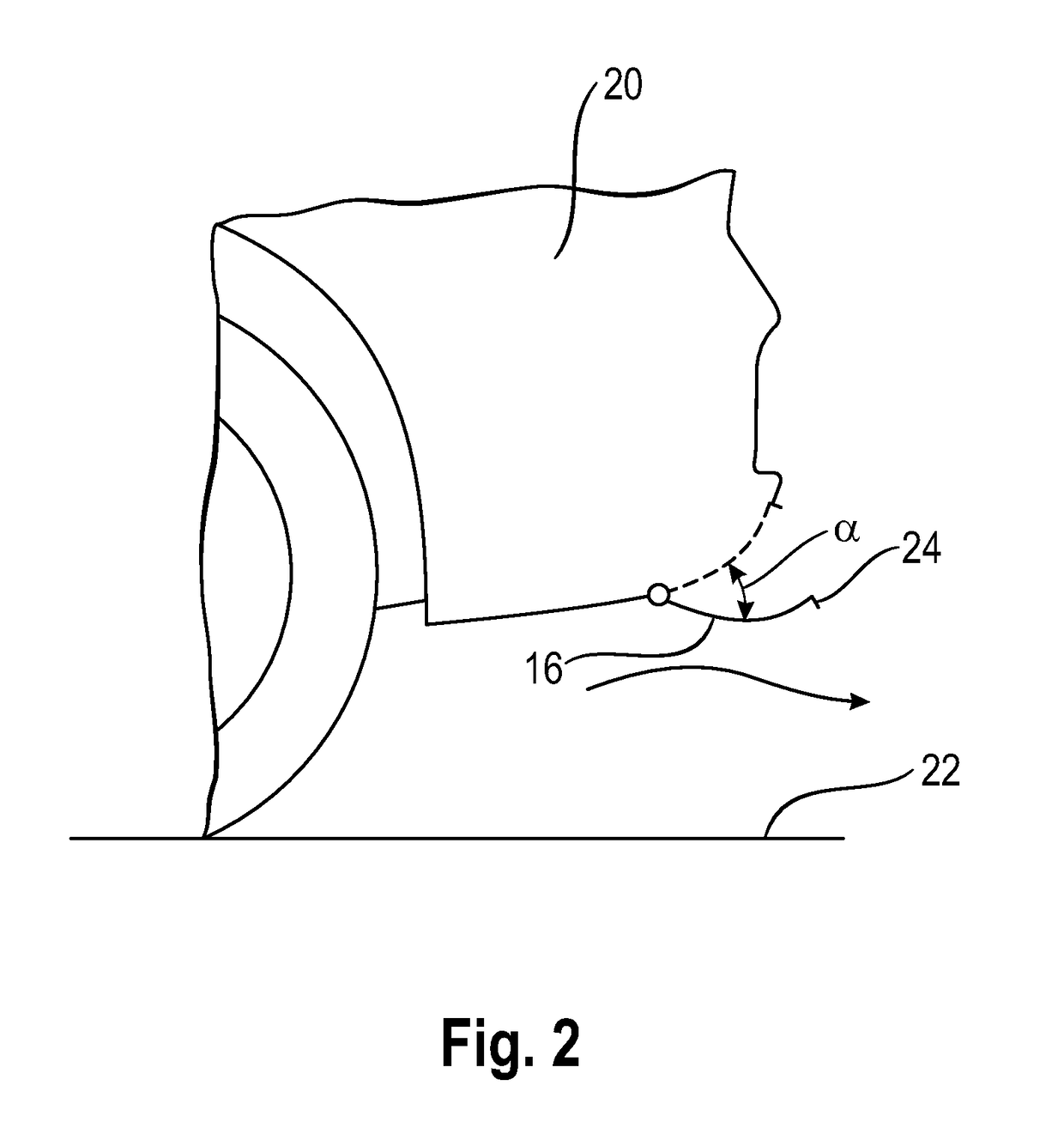
[0016]As can be clearly seen from a schematic view in FIG. 2, the flaps 16, 18 have a concavely curved surface that faces toward the lower rear end 20 of the motor vehicle 20 and that nests with the lower rear end when the flaps are in the retracted state. The convexly curved outer or lower and rearward facing surface of each flap conforms to the outer profile shape of the lower rear end 20 of the motor vehicle 20 when the flaps 16, 18 are in the retracted state, and in this retracted state, the curved surface yields an adequate overhang angle, and thus the necessary ground clearance. In the deployed state, the flaps 16, 18 ensure a virtually horizontal deflection of the air so that t...


PUM


Abstract

A rear-end diffuser arrangement for a motor vehicle has at least one flap (16, 18; 32) mounted on a body part (10) of the motor vehicle (2) so as to be movable by at least one drive device (38). The flap (16, 18; 32) is movable from a retracted state into a deployed state and vice versa. The at least one flap (16, 18; 32) has a concavely curved surface facing toward the vehicle rear end (20).

Description

CROSS REFERENCE TO RELATED APPLICATION[0001]This application claims priority under 35 USC 119 to German Patent Appl. No. 10 2015 118 076.6 filed on Oct. 23, 2015, the entire disclosure of which is incorporated herein by reference.BACKGROUND[0002]1. Field of the Invention[0003]The invention relates to a rear-end diffuser arrangement for a motor vehicle, having at least one flap mounted on a body part of the motor vehicle so as to be movable by way of at least one drive device, in such a way that the flap is movable from a retracted state into a deployed state and vice versa.[0004]2. Description of the Related Art[0005]Diffuser arrangements are well known from the prior art. They form active surfaces in the underbody region of a motor vehicle to improve aerodynamics. For example, a rear-end diffuser arrangement can significantly improve road grip, particularly during lateral acceleration maneuvers. More detailed explanations regarding the manner in which a rear-end diffuser operates i...

Claims


Application Information

Patent Timeline
IPC IPC(8): B62D35/02F15D1/00
CPCB62D35/02B62D37/02F15D1/007B62D35/007Y02T10/82
Inventor WOLF, THOMAS
Owner DR ING H C F PORSCHE AG
Why Eureka
Try Eureka