Probe module

a technology of probe module and probe, applied in the field of probe module, can solve problems such as potential signal loss, and achieve the effect of shortening the signal transmission path

Inactive Publication Date: 2017-04-27
MICROELECTRONICS TECH INC
View PDF15 Cites 1 Cited by
  • Summary
  • Abstract
  • Description
  • Claims
  • Application Information

AI Technical Summary

Benefits of technology

[0008]In view of the above, the primary objective of the present invention is...

Problems solved by technology

In other words, the longer the signal transmission path is, the higher the reactan...

Method used


Image

  • Probe module
  • Probe module
  • Probe module

Examples


first embodiment

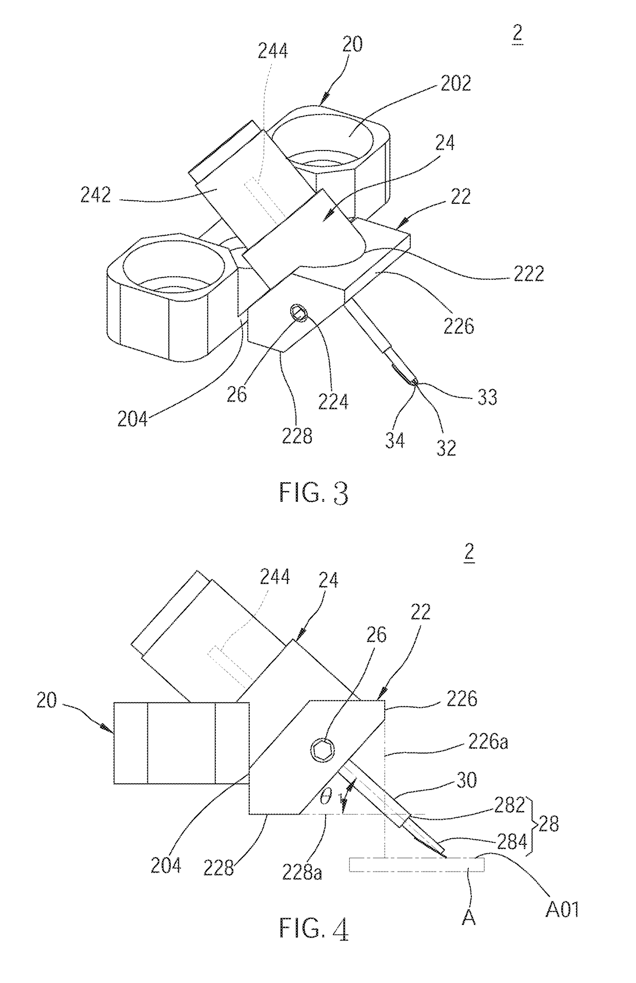
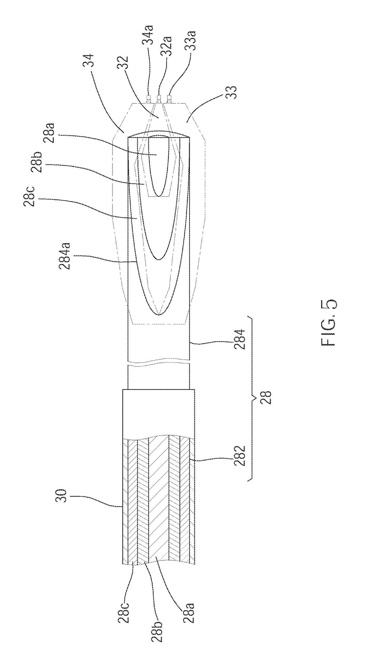
[0043]As shown in FIG. 3 and FIG. 5, a probe module 2 of the present invention, which is provided between a tester (not shown) and a device-under-test (DUT), wherein the DUT A has a tested surface A01. The probe module 2 includes a base 20, an engaging seat 22, a signal connector 24, an electrical signal transmitting member 28, and three probes 32-34.

[0044]The base 20 has two fixing holes 202, which are adapted to be passed by two screws (not shown) to fix the base 20 on the tester.

[0045]The engaging seat 22 is engaged with a front surface 204 of the base 20, and leans outward from the front surface 204 of the base 20. The engaging seat 22 has an engaging opening 222 and a side threaded hole 224, wherein the engaging opening 222 goes through the engaging seat 22 in a tilted manner, with a bottom thereof farther away from the base 20 than a top thereof. The side threaded hole 224 communicates with the engaging opening 222. In addition, the engaging seat 22 has a first end surface 226...

fifth embodiment

[0057]In addition, the probe module 6 further includes a reflector 80, which is provided on a side of the engaging seat 70 opposite to a front surface 682 of the base 68. In the fifth embodiment, the reflector 80 are provided on the engaging seat 70 through two connecting arms 82, wherein an end of each of the connecting arms 82 is fixedly connected to the engaging seat 70, while another end thereof is connected to the reflector 80. The connecting arms 82 are separated from each other by a distance to form an opening 822. The reflector 80 has a reflective surface 802 below the opening 822, wherein the reflective surface 802 is provided in a tilted manner and corresponding to the probes 76, whereby the reflective surface 802 could reflect an image of the probes 76 and the DUT A upward. A bottommost end of the reflector 80 is higher than the tips of the probes 76.

[0058]As shown in FIG. 15, by observing with a microscope or naked eyes from above the probe module 6, the locations of the...

sixth embodiment

[0060]The engaging seat 85 of the sixth embodiment is integrally connected to another end of the straight segment 844b. In addition, the engaging seat 85 also has a first end surface 852 and a second end surface 854. Differently, the first end surface 852 is tilted toward the base from a bottom edge 852a thereof to a top edge 852b thereof. An included angle θ3 between a first extending reference plane 852c of the first end surface 852 and the tested surface A01 of the DUT A is less than 90 degrees. An end edge 862a of a conductive ground 862 of a signal connector 86 aligns with the bottom edge 852a of the first end surface 852. Similarly, the second end surface 854 is the bottommost surface of the engaging seat 85, and aligns with a lower end of the straight segment 844b of the second body 844. A second extending reference plane 854a of the second end surface 854 is also parallel to the tested surface A01 of the DUT A.

[0061]Similar to the first embodiment, an absorbing sleeve 88 and...


PUM


Abstract

A probe module includes a base adapted to be fixed to a tester, an engaging seat engaged with the base, a signal connector, an electrical signal transmitting member, and two probes located below the engaging seat. The engaging seat has an engaging opening and a first end surface. The signal connector is provided in the engaging opening, and has a signal conductive portion and a conductive ground. A signal wire and a ground layer of the electrical signal transmitting member are electrically connected to the signal conductive portion and the conductive ground, respectively. The probes are electrically connected to the signal wire and the ground layer, respectively. The probes extend out of a first extending reference plane of the first end surface. Alternatively, a reflector is used to reflect an image of the probes upward. Whereby, a length of the electrical signal transmitting member can be further shortened.

Description

BACKGROUND OF THE INVENTION[0001]1. Technical Field[0002]The present invention relates generally to testing electronic components, and more particularly to a probe module.[0003]2. Description of Related Art[0004]To test if every electronic component of a device-under-test (DUT) is electrically connected correctly, a widely used method is to apply a probe module between a tester and the DUT to transmit test signals to the DUT.[0005]A conventional probe module 1 is illustrated in FIG. 1 and FIG. 2, which includes a base 10, an engaging seat 12, a signal connector 14, an electrical signal transmitting member 16, and a plurality of probes 18. The base 10 is adapted to be fixed to a tester (not shown). The engaging seat 12 is engaged with the base 10, and tilts downward. The engaging seat 12 has a front end surface 122 and a front end angle 124, wherein the front end surface 122 faces a DUT, and an included angle is formed between an extending reference plane 122a of the front end surfac...

Claims


Application Information

Patent Timeline
IPC IPC(8): G01R1/067G01R1/073
CPCG01R1/07342G01R1/06794G01R1/06711G01R31/2889
Inventor KU, WEI-CHENGHO, CHIH-HAOWEI, HAO
Owner MICROELECTRONICS TECH INC
Why Eureka
Try Eureka