Method for manufacturing a solar cell module and solar cell module

a manufacturing method and technology for solar cells, applied in photovoltaics, electrical devices, semiconductor devices, etc., can solve the problems of solar cell modules and power generation loss, and achieve the effect of solar cell arrays being blued

Inactive Publication Date: 2017-04-27
SOLARWORLD IND GMBH
View PDF2 Cites 9 Cited by
  • Summary
  • Abstract
  • Description
  • Claims
  • Application Information

AI Technical Summary

Benefits of technology

[0026]According to an improvement, a grid-shaped structure of the reflector is applied on the rear-side glass during the surface treatment by means of a grid-mask. In another configuration, the grid-shaped structure can also be applied without a mask by a controlled nozzle. Advantageously, the grid-structure can t...

Problems solved by technology

Therefore, the light striking in a gap of two adjacent solar cell...

Method used


Image

  • Method for manufacturing a solar cell module and solar cell module
  • Method for manufacturing a solar cell module and solar cell module
  • Method for manufacturing a solar cell module and solar cell module

Examples


first embodiment

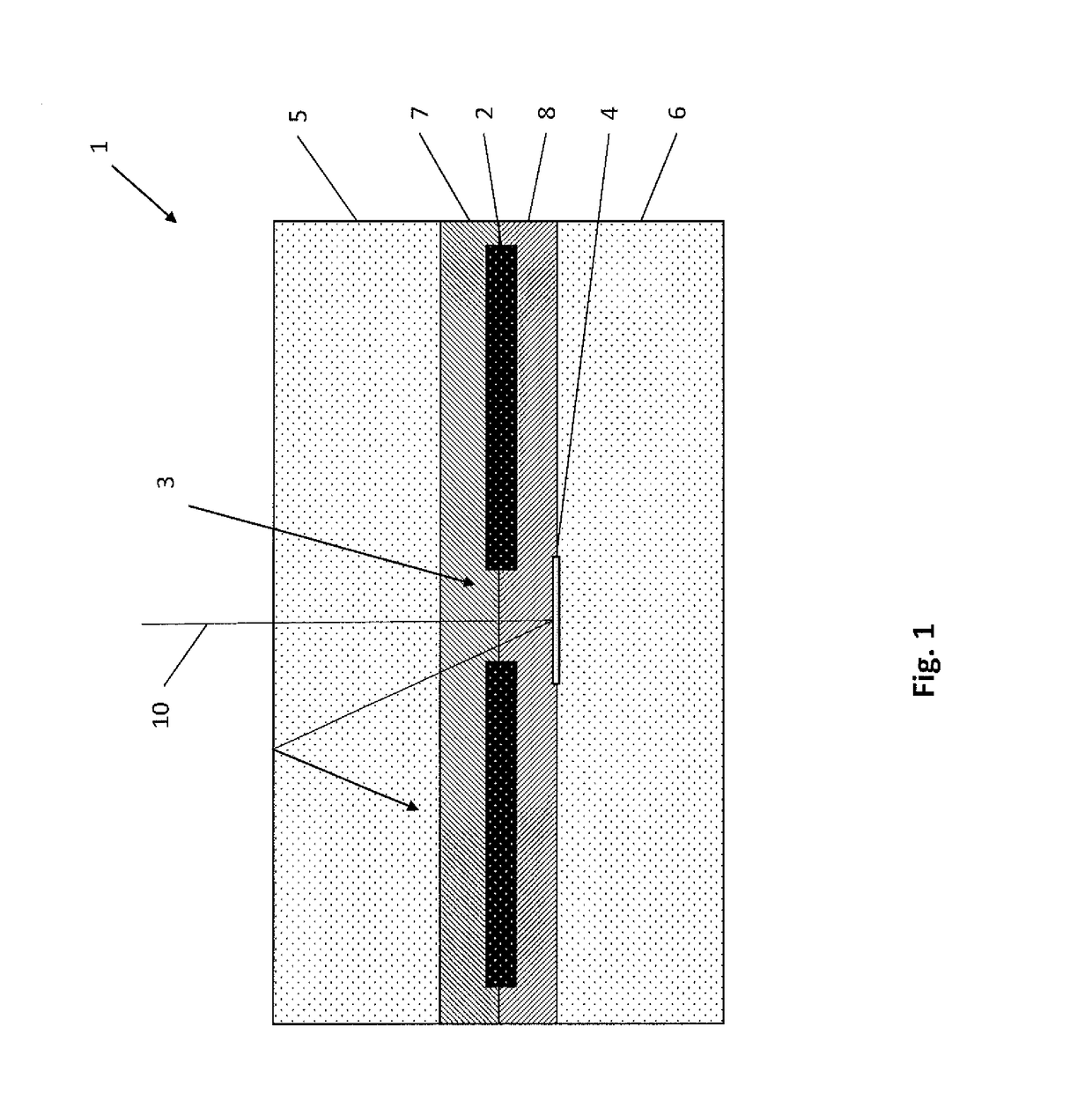
[0042]FIG. 1 shows a schematic cross-sectional representation of a solar cell module 1 according to a

[0043]The solar cell module 1 has two adjoining solar cells 2 in the depicted section of the section plane. A gap 3 is provided between the two solar cells 2. The number of two solar cells is purely as an example. Any higher number of solar cells 2 can also be provided, wherein a gap is respectively provided between two adjoining solar cells. Therefore, the depicted arrangement can safely proceed laterally with further solar cells in the same manner.

[0044]Both the solar cells 2 are embedded in the material of two plastic layers 7, 8. Thus, preferably it could be EVA coatings.

[0045]Further, a front surface layer 5 and back cover 6 close the solar cell module 1 from front and rear, i.e. in the section plane represented upwards and downwards. Therefore, it could

[0046]respectively be a glass layer or a film layer. Further, only the front surface 5 can also be provided as a glass layer an...

second embodiment

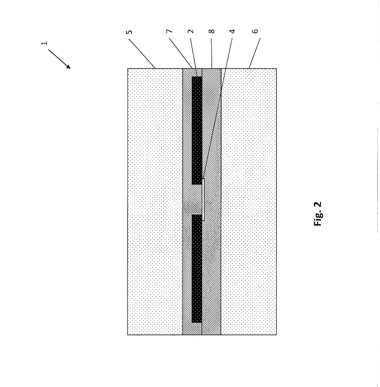
[0056]FIG. 2 shows a schematic cross-sectional representation of a solar cell module 1 according to a

[0057]In contrast to the first embodiment, here, the diffuse reflector 4 is disposed directly on a rear-side of the solar cells 2. Preferably, it could thus also be an adhesive tape or an adhesive film with white pigment coating.

[0058]During the manufacture, the reflector 4 is glued on the rear-side of the solar cells 2, before lamination.

third embodiment

[0059]FIG. 3 shows a schematic cross-sectional representation of a solar cell module 1 according to a

[0060]In this embodiment, the reflector 4 is configured as a rectangular body with a thickness spanning the distance between the back cover 6 and the solar cells 2. Thus, simultaneously it is flush with the back cover 6 and the solar cells 2.

[0061]Therefore, the reflector 4 can also be used here additionally as positioning aid for the solar cells 2, during lamination.

[0062]An additional stage could be provided on the reflector 4 for exact positioning of the solar cells 2.

[0063]For manufacturing, the lower plastic layer 8 is separately provided and the reflector 4 is inlaid therebetween. Subsequently, the solar cells 2 is disposed thereupon and the front plastic layer 7 is provided thereon. During lamination, the reflector 4 can then support the solar cells 2 on the rear-side thereof, so that these remain at the level of the reflector 4 in spite of a pressure applied during lamination...


PUM


Abstract

The present invention relates to a method for manufacturing a solar cell module by the steps of: providing at least two bifacial solar cells; adjoining arrangement of the solar cells, wherein a gap is provided between the solar cells; providing a diffuse reflector in the gap area. The present invention also relates to such a solar cell module, wherein the diffuse reflector is disposed and configured such that it diffusely reflects the incident light and a portion of the diffusely reflected lights strikes on the solar cell through total reflection at the front boundary layer of the solar cell module.

Description

FIELD OF INVENTION[0001]The present invention relates to a method for manufacturing a method for manufacturing a solar cell module and a solar cell module.TECHNICAL BACKGROUND[0002]Solar cell modules, also referred to as photovoltaic modules (PV-Modules), generally have several solar cells. A special type of solar cell module has so-called bifacial solar cells. Bifacial solar cells can absorb light on the front as well as on the rear-side and convert into electrical energy. Therefore, even reflected or indirect light on the rear-side of the solar cells can be converted in such solar cells and thereby the efficiency of the solar cells is increased.[0003]Solar cell modules with bifacial solar cells are referred to as bifacial solar cell modules. One of the Applicant's known bifacial solar cell module has a transparent front and rear-side. Therefore, the light striking in a gap of two adjacent solar cells passes through the solar cell module and is lost for power generation.SUMMARY OF ...

Claims


Application Information

Patent Timeline
IPC IPC(8): H01L31/0475H01L31/049H01L31/054
CPCH01L31/0475H01L31/049H01L31/0547H02S40/22H01L31/056Y02E10/52
Inventor ASBECK, FRANKHUND, MARKUSHAHN, HARALDGEORGI, MATTHIAS
Owner SOLARWORLD IND GMBH
Why Eureka
Try Eureka