
Earbud Monitoring Devices

a monitoring device and earbud technology, applied in the field of optical sensor devices, can solve the problems of inconvenient use, bulky, rigid, etc., and achieve the effect of improving heart rate monitoring consistency and lowering the sensitivity of optical signals

Active Publication Date: 2017-04-27
YUKKA MAGIC LLC
View PDF2 Cites 26 Cited by
  • Summary
  • Abstract
  • Description
  • Claims
  • Application Information

AI Technical Summary

Benefits of technology

Optical sensor modules in this patent can make it less sensitive to movement, which helps to make consistent heart rate monitoring across different subjects and types of exercise activities.

Problems solved by technology

However, traditional health monitors and environmental monitors may be bulky, rigid, and uncomfortable—generally not suitable for use during daily physical activity.
Unfortunately, spurious signals that may be difficult to isolate from a biometric signal are associated with physical movement (e.g., physical exercise, such as walking, running, daily activities, etc.) of a sensor relative to the user or the environment of the user (e.g., sunlight, room light, humidity, ambient acoustical or electromagnetic noise, temperature extremes or changes in temperature, etc.).
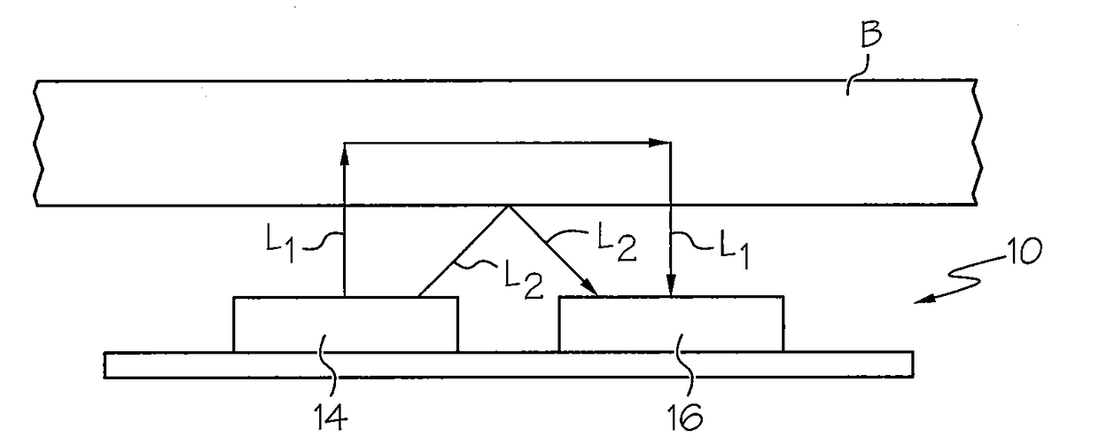
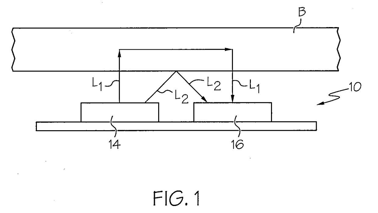
However, movement of the user can cause the sensor 10 to move relative to the body B such that light L2 can take a direct path from the optical source 14 into the optical detector 16 (for example by reflection off of the body, i.e., the skin, of the user), which increases spurious signals.
Moreover, motion artifacts may cause the distance between the sensor 10 and body B to change in time, thereby modulating L1 and L2 in time, leading to motion artifact noise on the signal generated by the detector 16.

Method used


Image

  • Earbud Monitoring Devices
  • Earbud Monitoring Devices
  • Earbud Monitoring Devices

Examples


Embodiment Construction

[0073]The present invention will now be described more fully hereinafter with reference to the accompanying figures, in which embodiments of the invention are shown. This invention may, however, be embodied in many different forms and should not be construed as limited to the embodiments set forth herein. Like numbers refer to like elements throughout. In the figures, certain layers, components or features may be exaggerated for clarity, and broken lines illustrate optional features or operations unless specified otherwise. In addition, the sequence of operations (or steps) is not limited to the order presented in the figures and / or claims unless specifically indicated otherwise. Features described with respect to one figure or embodiment can be associated with another embodiment or figure although not specifically described or shown as such.

[0074]It will be understood that when a feature or element is referred to as being “on” another feature or element, it can be directly on the o...


PUM


Abstract

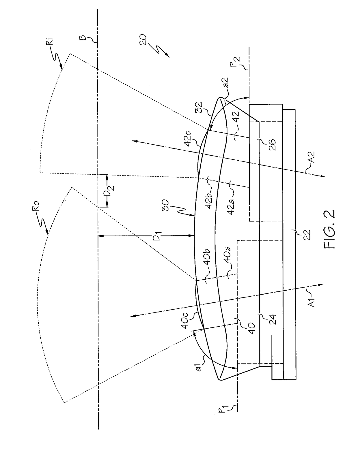
An earbud includes a speaker driver, and a sensor módule secured to the speaker driver that is configured to detect and / or measure physiological information from a subject wearing the earbud. The sensor module includes a printed circuit board, an optical source secured to the printed circuit board, and an optical detector secured to the printed circuit board. A first light guide may be coupled to the optical source that is configured to deliver light from the optical source into an ear region of the subject via a distal end thereof. A second light guide may be coupled to the optical detector that is configured to collect light from the ear region via a distal end thereof and deliver collected light to the optical detector. One or more additional sensors may be secured to the speaker driver, such as accelerometers, humidity sensors, altimeters, and temperature sensors.

Description

RELATED APPLICATIONS[0001]This application is a continuation of U.S. patent application Ser. No. 15 / 324,139, filed Jan. 5, 2017, which is a 35 U.S.C. §371 national stage application of PCT Application No. PCT / US2015 / 041562, filed on Jul. 22, 2015, which claims the benefit of and priority to U.S. Provisional Patent Application No. 62 / 033,922 filed Aug. 6, 2014, the disclosures of which are incorporated herein by reference as if set forth in their entireties.FIELD OF THE INVENTION[0002]The present invention relates generally to monitoring devices and, more particularly, to optical sensor devices.BACKGROUND OF THE INVENTION[0003]There is growing market demand for personal health and environmental monitors, for example, for gauging overall health and metabolism during exercise, athletic training, dieting, daily life activities, sickness, and physical therapy. However, traditional health monitors and environmental monitors may be bulky, rigid, and uncomfortable—generally not suitable for...

Claims


Application Information

Patent Timeline
Patent Type & Authority Applications(United States)
IPC IPC(8): H04R1/10A61B5/026A61B5/1455A61B5/00
CPCH04R1/1091H04R1/1016A61B5/6803A61B5/6802A61B5/1455A61B5/721A61B5/0261A61B5/6898A61B5/14552A61B2562/0233A61B2562/0238A61B5/6815A61B5/02427
Inventor WAGNER, WOLFGANGSTEPHENSON, SHAWNJUST, STEVEN MATTHEWAUMER, MICHAEL EDWARDTUCKER, JESSE BERKLEYESCHBACH, LAWRENCE CHRISTOPHERLEBOEUF, STEVEN FRANCIS
Owner YUKKA MAGIC LLC
Learn More