

Imaging lens system
a technology of imaging lens and lens body, which is applied in the field of imaging lens system, can solve the problems of increasing the sensitivity of the system, affecting the image quality, and the system will generate more aberrations, so as to achieve the effect of reducing the size of the imaging lens system, reducing the sensitivity of the optical system, and improving the quality of imag
- Summary
- Abstract
- Description
- Claims
- Application Information
AI Technical Summary
Benefits of technology
Problems solved by technology
Method used
Image


Examples
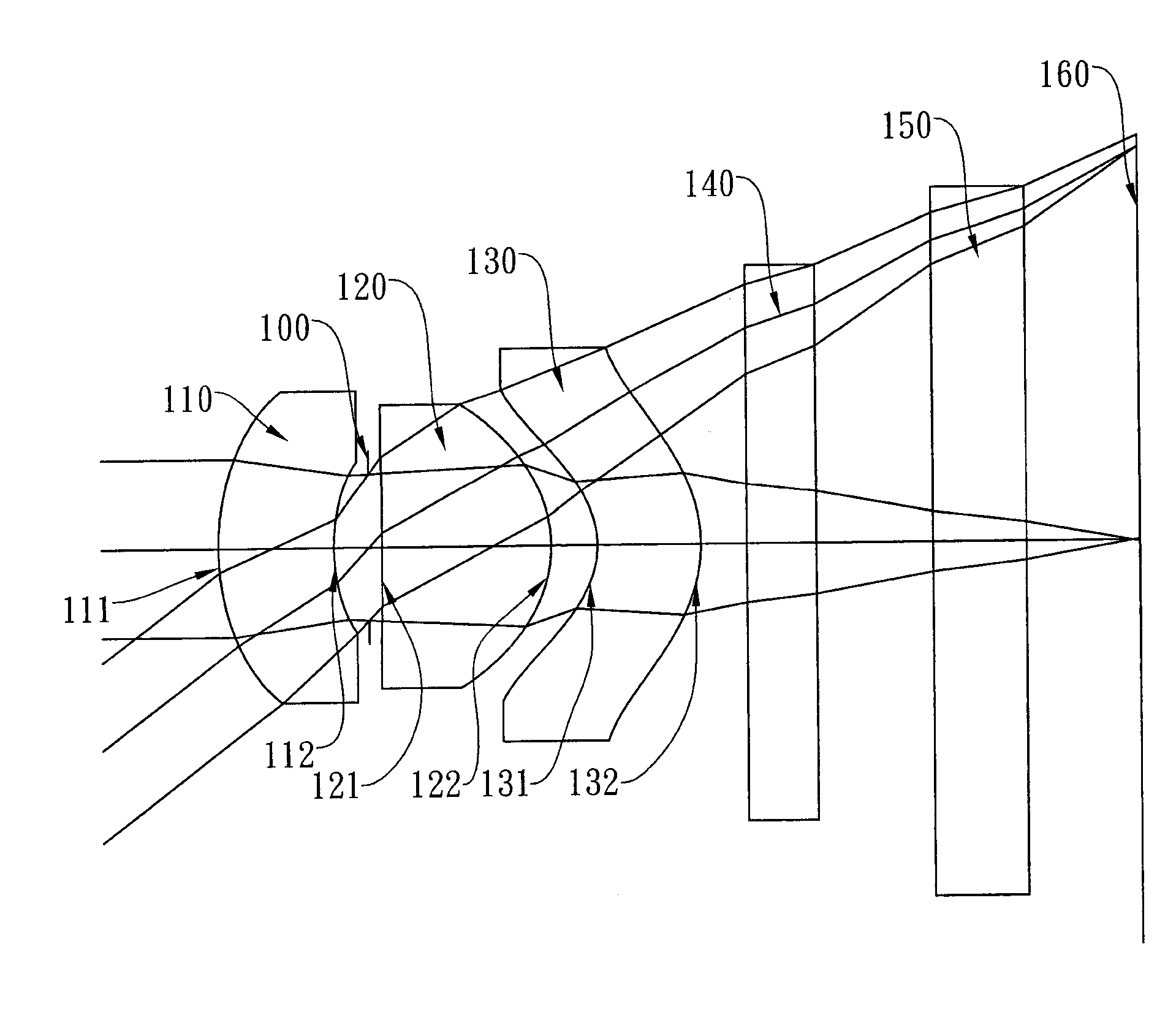
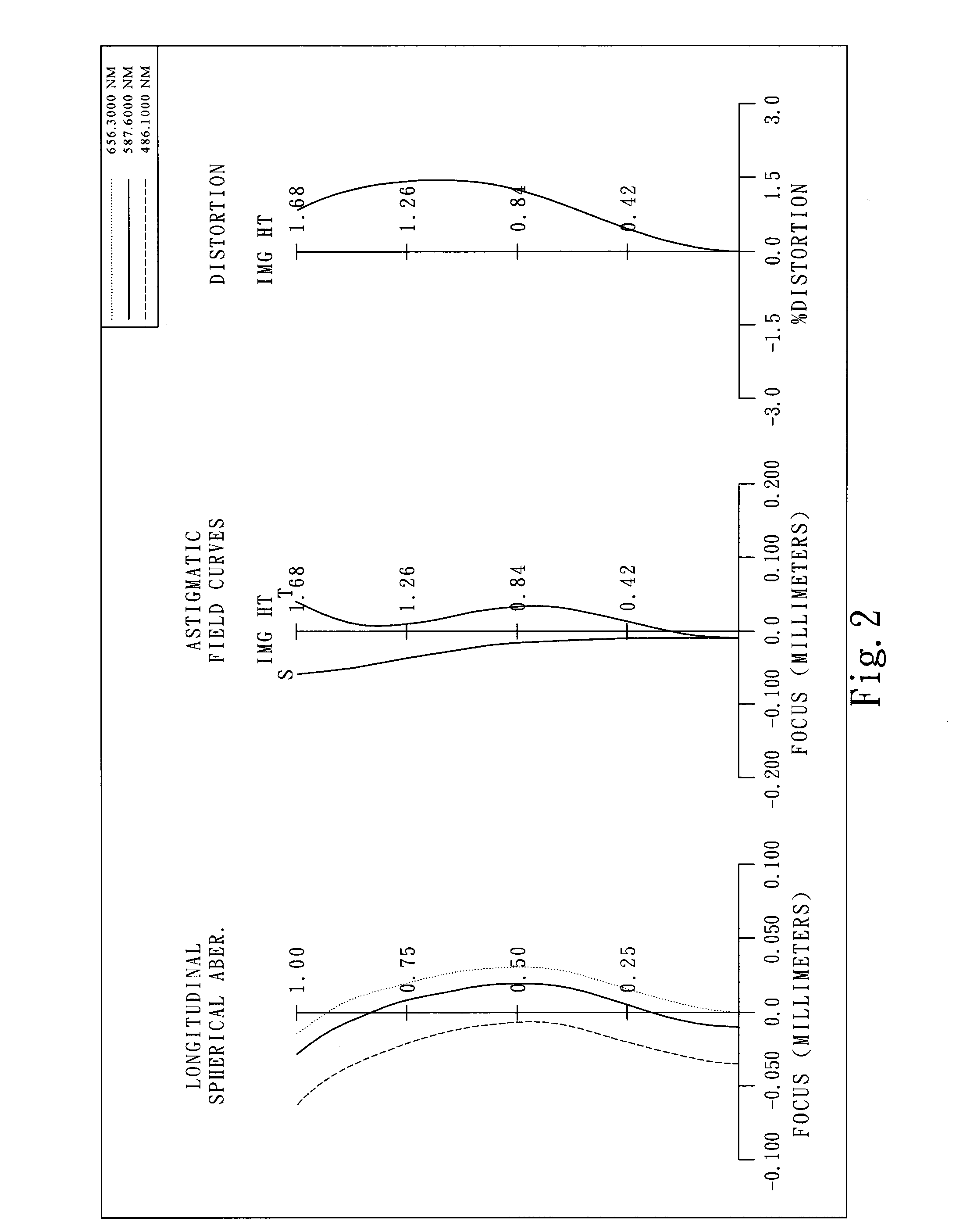
first embodiment
[0063]In the present imaging lens system, the focal length of the imaging lens system is f, and it satisfies the relation: f=2.17 (mm).
[0064]In the first embodiment of the present imaging lens system, the f-number of the imaging lens system is Fno, and it satisfies the relation: Fno=2.85.
[0065]In the first embodiment of the present imaging lens system, half of the maximal field of view of the imaging lens system is HFOV, and it satisfies the relation: HFOV=37.5 deg.
[0066]In the first embodiment of the present imaging lens system, the Abbe number of the first lens element 110 is V1, the Abbe number of the second lens element 120 is V2, and they satisfy the relation: V2−V1=32.5.
[0067]In the first embodiment of the present imaging lens system, the thickness on the optical axis of the second lens element 120 is CT2, and it satisfies the relation: CT2=0.73(mm).
[0068]In the first embodiment of the present imaging lens system, the focal length of the imaging lens system is f, the distance ...
second embodiment
[0081]In the present imaging lens system, the focal length of the imaging lens system is f, and it satisfies the relation: f=2.34 (mm).
[0082]In the second embodiment of the present imaging lens system, the f-number of the imaging lens system is Fno, and it satisfies the relation: Fno=2.80.
[0083]In the second embodiment of the present imaging lens system, half of the maximal field of view of the imaging lens system is HFOV, and it satisfies the relation: HFOV=31.7 deg.
[0084]In the second embodiment of the present imaging lens system, the Abbe number of the first lens element 310 is V1, the Abbe number of the second lens element 320 is V2, and they satisfy the relation: V2−V1=0.0.
[0085]In the second embodiment of the present imaging lens system, the thickness on the optical axis of the second lens element 320 is CT2, and it satisfies the relation: CT2=0.63(mm).
[0086]In the second embodiment of the present imaging lens system, the focal length of the imaging lens system is f, the dista...
third embodiment
[0099]In the present imaging lens system, the focal length of the imaging lens system is f, and it satisfies the relation: f=2.53 (mm).
[0100]In the third embodiment of the present imaging lens system, the f-number of the imaging lens system is Fno, and it satisfies the relation: Fno=3.00.
[0101]In the third embodiment of the present imaging lens system, half of the maximal field of view of the imaging lens system is HFOV, and it satisfies the relation: HFOV=30.0 deg.
[0102]In the third embodiment of the present imaging lens system, the Abbe number of the first lens element 510 is V1, the Abbe number of the second lens element 520 is V2, and they satisfy the relation: V2−V1=0.0.
[0103]In the third embodiment of the present imaging lens system, the thickness on the optical axis of the second lens element 520 is CT2, and it satisfies the relation: CT2=0.38 (mm).
[0104]In the third embodiment of the present imaging lens system, the focal length of the imaging lens system is f, the distance ...
PUM
 Abstract
Description
Claims
Application Information