Method and apparatus for particle sorting

a particle sorting and particle technology, applied in the field of particle sorting methods and apparatuses, can solve the problems of difficult use, low delivery accuracy, and high cost of cell sorting apparatuses, and achieve the effect of small area, effective and precise sorting

Inactive Publication Date: 2017-05-04
NAMOCELL INC
View PDF3 Cites 14 Cited by
  • Summary
  • Abstract
  • Description
  • Claims
  • Application Information

AI Technical Summary

Benefits of technology

[0010]In general, described herein are apparatus (e.g., systems and devices) and methods for sorting microparticles for effectively and precisely sorting and dispensing individual microparticles, such as a single cell or small group of cells, to a very small area. These methods and apparatus do not require complex fluidic and control systems. In particular, described herein are flow switches that may be used to differentially sorting microparticles based on the flow rate of the microparticle and / or the flow rate of the fluid surrounding the microparticle. These flow switches differentially directs a fluid flowing through the flow switch based on the flow rate of the fluid. Further, these flow switches may be used in conjunction with an identification and control module which can determine when a microparticle having predetermined properties is within the flow switch, and can increase (or decrease) the flow rate of the fluid carrying the microparticle to sort the microparticle. As used herein, a flow switch is a switch that sorts a material between two (or more) outputs from the flow switch based on the flow rate of material as it passes through the flow switch. In particular, the flow switches described herein may achieve differential flow sorting based on the differences between the resistance to flow through the outputs and different static fluid pressure at the interface between each output and the flow switch (e.g., the flow switch convergence region).
[0013]In addition, any of the apparatus described herein may include features that prevent disruptions in the flow rate (e.g., preventing unintentional or uncontrolled changes in flow rate, such as turbulence) for fluid within the flow switch. Also, any of these systems may include a degasser to remove bubbles or to prevent bubble formation. Further, the flow paths through the flow switch may be configured to prevent or reduce turbulent flow.
[0016]The apparatus described herein may also be configured so that they can be primed or prepared for operation. For example, a low liquid flow rate in microfluidic structure during system priming may be overcome by reversing the flow in the microfluidic structure and by backfilling with air which has much lower flow resistance than liquid.
[0025]The methods and apparatus for sorting microparticles described herein may also be referred to as continuous-flow, because the stream of fluid containing the microparticles may be continuously held within the flow switch, without forming a droplet that is then deflected / sorted. This may allow more precise positioning of the sorted material, e.g., into 96 well plates, etc., as the microparticle and fluid surrounding it are deposited from a fluidic outlet of the flow switch into a target (e.g., multi-well plate).
[0032]In general, the flow rates though the flow switch may be determined in part by the geometry of the flow paths. For example, in some variations the diameter of the second flow path is greater than the diameter of the first flow path. This may allow for the addition of fluid moving at a different (e.g., faster) rate than the fluid surrounding a microparticle; thus the resulting change in the flow rate of the fluid surrounding the microparticle may allow sorting of the microparticle by the flow switch.

Problems solved by technology

All of these methods typically involve complex fluidic systems and sophisticated electrical control systems, which make cell sorting apparatus expensive to build, and difficult to use.
Unfortunately, droplet sorting is typically limited to delivery of sorted individual cells to a relative large area (e.g., more than 5 mm in diameter); for areas smaller than 5 mm in diameter, the deliver accuracy becomes very low because droplets typically travel at speed more than 1 m / s and to aim the droplets precisely to an area less 5 mm in diameter (e.g., using electrostatic force) is very difficult, particularly the speed of droplet is not constant.
However, sorting individual cell into 384-well cell culture plate which is about 3 mm in diameter is not practical.
Unfortunately, such liquid dispensers cannot sort cells.

Method used


Image

  • Method and apparatus for particle sorting
  • Method and apparatus for particle sorting
  • Method and apparatus for particle sorting

Examples


Embodiment Construction

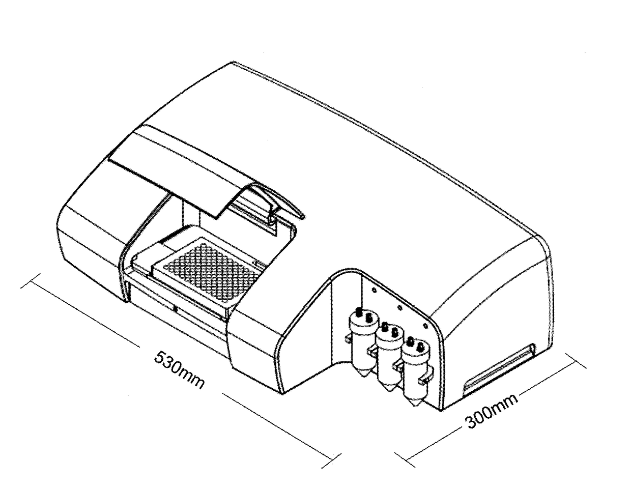
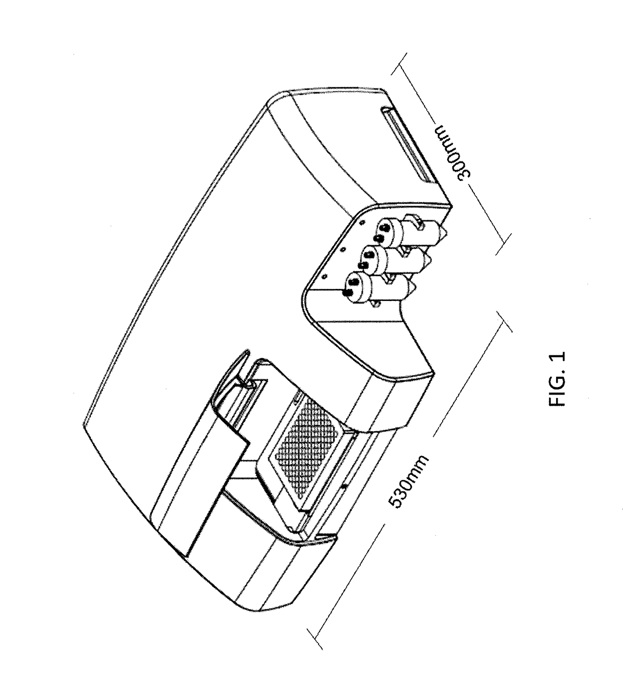
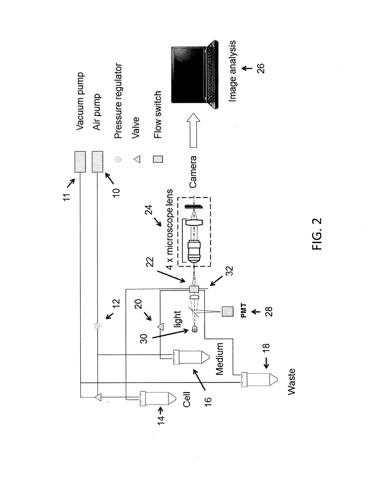
[0042]Described herein are apparatus and methods for sorting microparticles surrounded by fluid using a flow switch that sorts detected microparticles based on the flow rate (speed) of the fluid surrounding the microparticle.

[0043]For example, a method of sorting microparticles may include alternating fluidic flow path using a flow switch which contains at least one inlet and at least two outlets, wherein alternating fluidic flow path is achieved by changing flow rate into the flow switch system. In some variations the flow switch includes at least two inlets and at least two outlets. The method may include maintaining one flow path at low flow rate wherein the pressure in one flow outlet is kept lower than that in the other flow outlet. The flow switch may also have a lower pressure in one flow outlet as compared to the other flow outlet, for example, by lowing the opening of one flow outlet as compared to that of the other flow outlet. The other flow path may be maintained at high...


PUM

PropertyMeasurementUnit
diameteraaaaaaaaaa
speedaaaaaaaaaa
diameteraaaaaaaaaa

Abstract

Apparatus and methods for sorting and dispensing microparticles using a flow switch mechanism wherein changing flow rate into the flow switch changes flow path. The present invention is well-suited for precisely sorting microparticles, such as cells, for applications such as cell line development, monoclonal antibody selection and single cell research, etc.

Description

CROSS REFERENCE TO RELATED APPLICATIONS[0001]None.INCORPORATION BY REFERENCE[0002]All publications and patent applications mentioned in this specification are herein incorporated by reference in their entirety to the same extent as if each individual publication or patent application was specifically and individually indicated to be incorporated by reference.FIELD[0003]Described herein are apparatus (devices and systems) and methods for automatically sorting and dispensing microparticles, such as single cells. These techniques may be particularly useful for biological and medical applications.BACKGROUND[0004]Flow cytometry is used to differentiate various types of cells and other similar small particles. Conventional flow cytometers commonly comprise an optically-transparent flow cell, usually made of quartz, having a central channel through which a stream of cells to be individually identified is made to flow. Movement of the cell stream through the flow cell channel is hydrodynami...

Claims


Application Information

Patent Timeline
Patent Type & Authority Applications(United States)
IPC IPC(8): G01N15/14B01L3/00
CPCG01N15/1484G01N2015/1006G01N15/1459B01L3/502715B01L3/502761B01L3/502738B01L3/50273G01N2015/149B01L2200/0652B01L2300/14B01L2300/0627B01L2300/0867B01L2200/0605B01L2400/0487G01N15/1463G01N2015/1081B01L3/0241B01L3/502784B01L2200/0673B01L2200/0684B01L2300/0816G01N15/147
Inventor LIN, JUNYU
Owner NAMOCELL INC
Why Eureka
Try Eureka