Apparatus for indirect atmospheric pressure plasma processing

Inactive Publication Date: 2017-05-04
VLAAMSE INSTELLING VOOR TECHNOLOGISCH ONDERZOEK NV VITO
View PDF10 Cites 3 Cited by
  • Summary
  • Abstract
  • Description
  • Claims
  • Application Information

AI Technical Summary

Benefits of technology

[0007]An objective of aspects of the present invention is to overcome one or more of the above drawbacks. One objective of aspects of the invention is to improve uniform and homogeneous plasma processing of the substrate surface. Another objective of aspects of the invention is enabling a prolonged and mor

Problems solved by technology

The resulting superimposition of high drift velocity in the process gas flow and the inherent diffusion movement results in a prolonged displacement distance of activated species into the treatment zone.
A drawback of the above apparatus is

Method used


Image

  • Apparatus for indirect atmospheric pressure plasma processing
  • Apparatus for indirect atmospheric pressure plasma processing
  • Apparatus for indirect atmospheric pressure plasma processing

Examples


Embodiment Construction

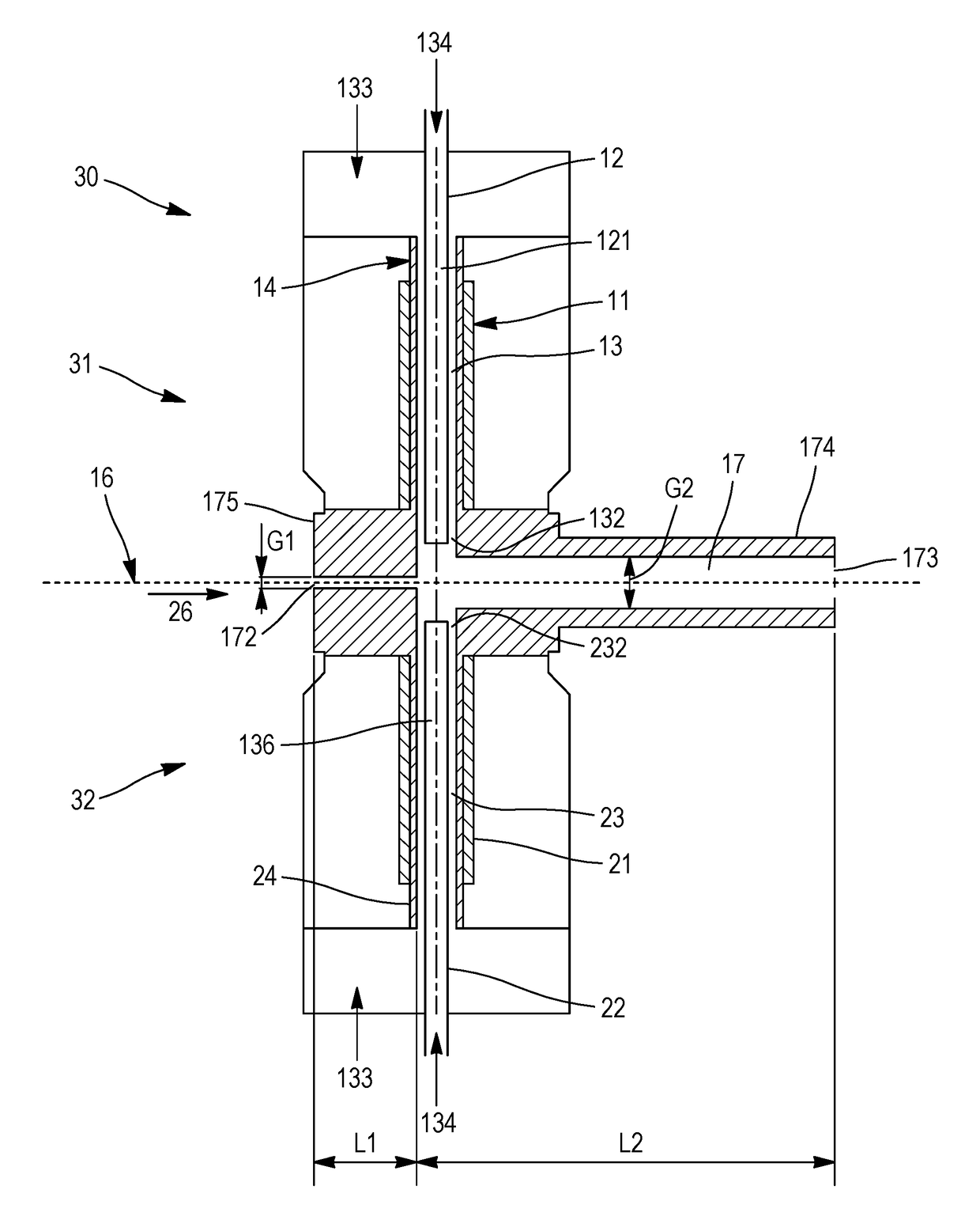
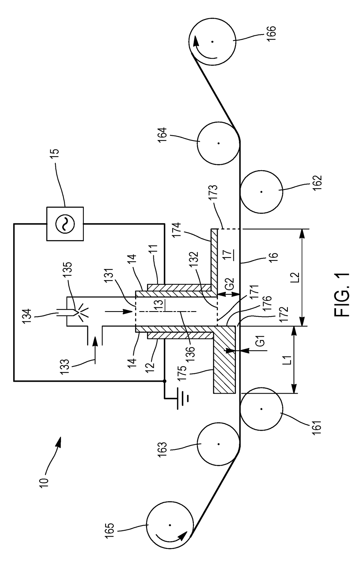
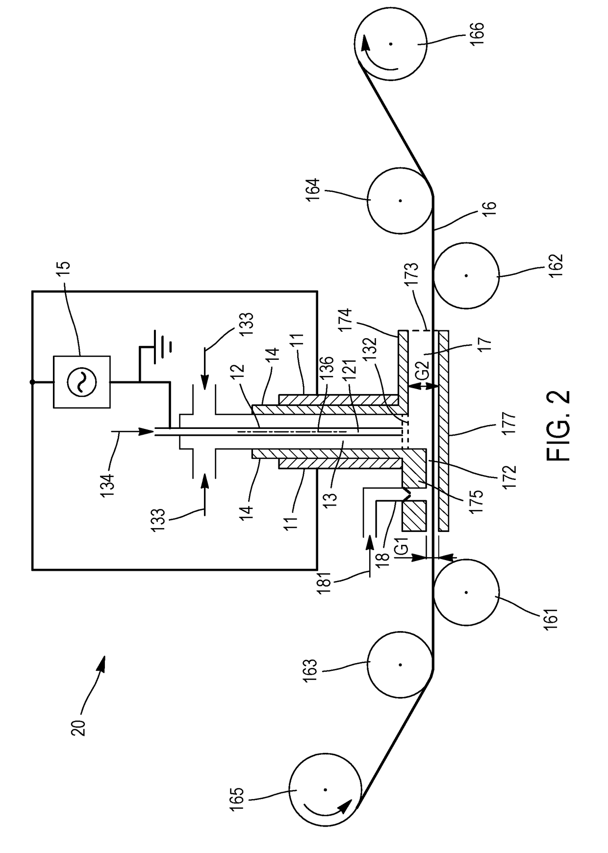
[0020]Referring to FIG. 1, an apparatus 10 for plasma processing of a continuous substrate 16, such as but not limited to films and foils, comprises a pair of oppositely arranged electrodes 11 and 12. Electrodes 11 and 12 are planar and extend parallel to each other. They are spaced apart to define a plasma discharge chamber 13 between the electrodes 11, 12. Advantageously, dielectric layers 14 cover one or both electrodes 11, 12 at the side facing the plasma discharge chamber 13. In such case, the dielectric layers 14 form walls of the chamber 13. Dielectric materials include borosilicate glass, quartz, and alumina.

[0021]Chamber 13 comprises an inlet 131 through which a plasma forming gas 133 is made to enter the chamber. The plasma forming gas is one which is able to create a plasma discharge in chamber 13 under an electric field generated by the electrodes 11, 12. The plasma forming gas is advantageously a non-oxidizing gas, advantageously a gas which is substantially oxygen-free...


PUM


Abstract

Apparatus for plasma processing of a continuous fiber, comprising a first and a second plasma torch. Each plasma torch comprises oppositely arranged electrodes to define a plasma discharge chamber between the electrodes. The plasma discharge chamber comprises an inlet and an outlet for passing a plasma forming gas between the electrodes. The apparatus further comprises an afterglow chamber in fluid communication with the outlets of the plasma discharge chambers, which comprises a substrate inlet and a substrate outlet arranged at opposite sides of the outlets of the plasma discharge chambers. A transport system is configured to continuously transport the fiber from the substrate inlet to the substrate outlet through the afterglow chamber. The substrate inlet comprises an aperture having a cross-sectional size substantially smaller than a cross-sectional size of the afterglow chamber. The outlets of the plasma torches face each other and exhaust plasma activated species into the afterglow chamber.

Description

CROSS-REFERENCE TO RELATED APPLICATION[0001]This application claims priority to European Patent Application No. 15191844.8, filed Oct. 28, 2015, which is hereby incorporation by reference.FIELD OF THE INVENTION[0002]The present invention is related to apparatuses and methods for indirect atmospheric pressure plasma processing, in particular where the substrate to be plasma processed is kept remote from the plasma discharge zone.[0003]With indirect or remote plasma treatment of substrates, as opposed to in-situ plasma treatment, the substrate is not passed through the plasma discharge zone, in which an atmospheric pressure plasma is maintained between electrodes and activated species are formed. Instead, the substrate is positioned at a location remote from the plasma discharge zone and the plasma-activated species are transported to the remote location where they are made to react with the substrate. Remote plasma treatment is often preferred over in-situ treatment, in particular fo...

Claims


Application Information

Patent Timeline
IPC IPC(8): H01J37/32
CPCH01J37/32532H01J37/3244H01J37/32009H05H2240/10H05H1/246H05H1/2431H05H2245/40H05H1/245
Inventor VANHULSEL, ANNICKVAN HOOF, ERWINCOOLS, JAN
Owner VLAAMSE INSTELLING VOOR TECHNOLOGISCH ONDERZOEK NV VITO
Why Eureka
Try Eureka