

Push-On Clip
- Summary
- Abstract
- Description
- Claims
- Application Information
AI Technical Summary
Benefits of technology
Problems solved by technology
Method used
Image


Examples
Embodiment Construction
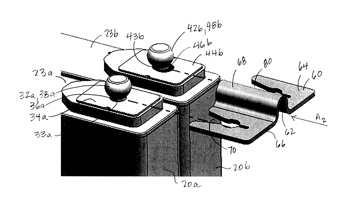
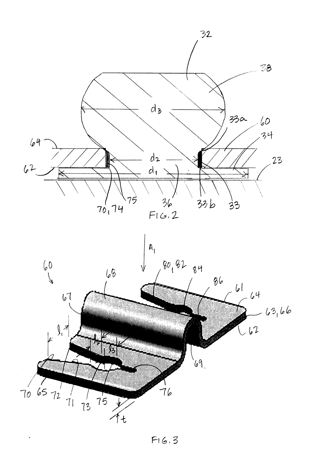
[0018]Referring to FIG. 1, a battery system 10 used to provide electrical power includes prismatic electrochemical cells 20 that are electrically interconnected and stored in an organized manner within a battery pack housing 12. The term “prismatic” as used herein refers to having a rectangular shape. The cells 20 are arranged in a side-by-side configuration to form a stack 18, and several cells 20 in the stacked arrangement are bundled together to form a battery module 15. Within the battery module 15, the stacked group of cells 20 may be commonly supported on a support plate 17 and bound together under compression via a band 16. Although the illustrated embodiment of the battery module 15 includes six cells 20, battery modules 15 may include a greater or fewer number of cells 20. Several battery modules 15 are collected into subunits 14, and several subunits 14 are arranged within the battery pack housing 12. The cells 20 are connected electrically in series or in parallel using e...
PUM
 Abstract
Description
Claims
Application Information