
Method for making a slip resistant mat

a technology of anti-skid or anti-creep mats and mats, which is applied in the direction of coatings, flat articles, other domestic articles, etc., can solve the problems of lack of any device or feature intended to secure the mat in place, the mats that were not skid resistant on smooth floors, and the back of the mat becomes a sliphazard, etc., to achieve the effect of reducing costs, reducing manufacturing costs, and ensuring the effect of stability

Active Publication Date: 2017-05-11
CINTAS CORP SERVICES INC
View PDF3 Cites 0 Cited by
  • Summary
  • Abstract
  • Description
  • Claims
  • Application Information

AI Technical Summary

Benefits of technology

[0015]One advantage of this invention is that the mat resists slipping to a much greater extent than existing mat designs even in the presence of moisture between the mat and the floor. Another advantage is that it provides the enhanced slip-resistance without adding any weight or installation complexity to existing mat designs. Another advantage is that the invention does not require any permanent fastening means and is therefore easy to move to different locations. Another advantage is that the channels provide additional cushioning for pedestrian and vehicular traffic. Another advantage is that the cushioning of the channels yields an anti-fatigue effect, thereby resulting in reduced wear and tear and routine maintenance and increased user comfort, especially for locally stationed employees spending long period of time on the mat. Another advantage of the invention is that the slip-resistance is effective on a wide variety of surfaces.
[0016]In other embodiments, this invention is generally drawn to a system and method for making a slip resistant mat. More particularly, the system and method can include assembling parts with predetermined geometries to form a mold screen that can be used for making slip resistant mats that have channels or other features. Each part of the mold screen can have predetermined geometrical shapes that can be manufactured efficiently and with reduced cost.
[0017]The raw material used to form the slip resistant mat may comprise rubber as is well known in the art. According to one exemplary embodiment, the mold system of this invention allows for the rubber to have a predefined geometry which includes the channels or other features. This predefined geometry includes regions of rubber that are positioned to correspond with the channels in the platen.
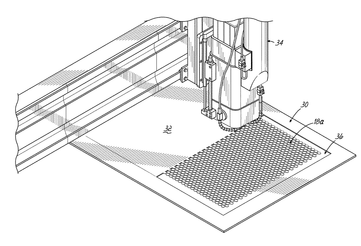
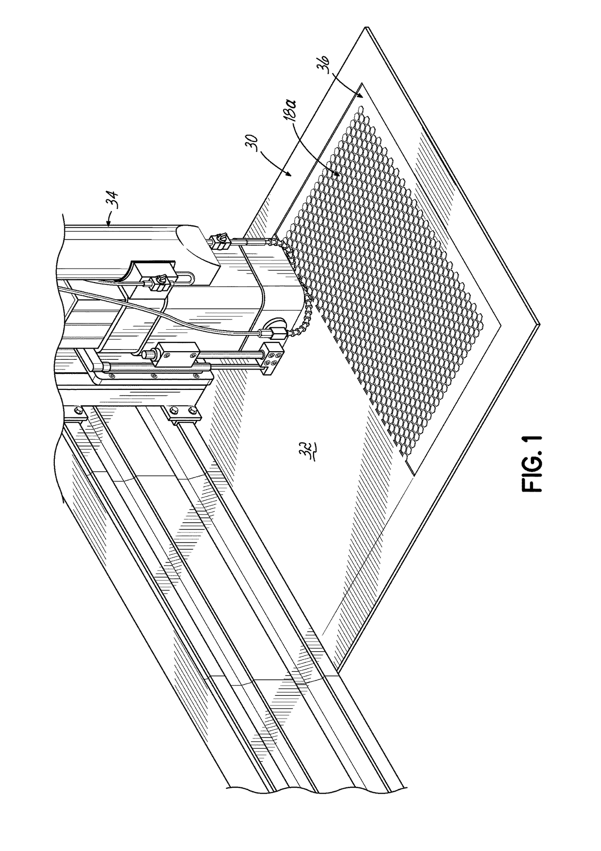
[0018]One part of the system to make the mat can include a model platen. The model platen may comprise a metal sheet that has a replica of the plurality of channels that form a surface of the metal sheet. The replica channels can be shaped to replicate the basic structure of the slip resistant pattern on the mat backing. The channels can be formed by a process that employs a computer numerical controlled (CNC) machine. By using a CNC machine for forming the model platen, the model platen can be made very efficiently, precisely and with reduced cost compared to conventional machining methods.
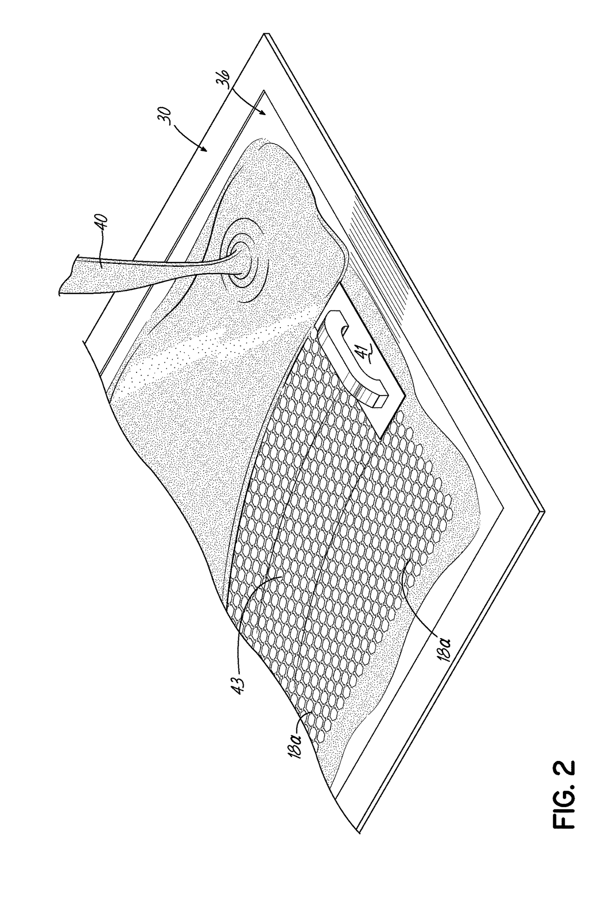
[0019]According to one aspect of this invention, a casting system is used in which the aluminum plate or model platen is machined with CNC routers. The machined model platen is used to create a mold screen which has a negative of the slip resistant pattern on the mat backing. Using a negative means that the CNC machine formed replica channels are very thin and do not affect the integrity of the model platen or mold screen. A blend of silicone, with a reinforcing backing of Nomex® or Kevlar®, may be used to create the mold screen.
[0020]The replica pattern created in the model platen may be only 0.25 inches deep and 0.045 inches wide. The replica channel pattern is a continuous series of lines which would not have been possible to create with known manufacturing techniques. The negative of the channel pattern is created in the mold screen. Using continuous channel lines and silicone, the issue of air entrapment can be avoided which to date has been an issue with patterns that have small objects and tolerances. The mold screen with a negative pattern of the channels is then used to manufacture the mat backing with the slip resistant channel pattern, similar to that machined into the model platen.

Problems solved by technology

However, both of these approaches resulted in floor mats that were not skid resistant on smooth floors, especially those floors with residual moisture under the mat, perhaps from the moping of the floor and then the mat being replaced, or the mat being slightly damp when delivered and rolled out.
In such cases, the water on the back of the mat becomes a slip hazard.
For the smooth back mats, movement of the mat results from similar forces and the lack of any device or feature intended to secure the mat in place.
While this approach is well-developed, it results in floor mats that are difficult or impossible to move from place to place and the structures required to attach the mat add cost to the mat and difficulty to the installation.
If the frame is fastened or embedded, the other problems mentioned above still remain.
While this approach provides acceptable slip-resistance for light shower and bath mat applications, traditional suctions cups are not sufficient to provide sufficient anti-skidding forces to prevent slipping and movement in high traffic and high load areas.
Traditional suction cups also result in a wavy mat surface which is more difficult for individuals and loads to traverse.
As mentioned, existing approaches to reducing movement of mats include significant limitations.
Further, the known approaches require additional space, components, installation effort and expense.
In addition to the problem of slip resistant mats moving when traversed by heavy loads or wheeled carts, another drawback of known slip resistant mats relates to the manufacturing process of these mats.
When the grippers are wet, the potential for mat slippage and possible resulting injuries increase.
The more metal that is removed with punching, the less resilient it is to being deformed and once bent, it is of no use in the manufacturing process.
This has limited the open area of the screens and meant that there is a physical limit on the pattern on the back of the mat.
Conventional manufacturing techniques have not addressed these problems often associated with conventional slip resistant mats and the associated systems and methods for mat production.

Method used


Image

  • Method for making a slip resistant mat
  • Method for making a slip resistant mat
  • Method for making a slip resistant mat

Examples


Embodiment Construction

[0030]A slip resistant mat, system and method for making such a mat can include assembling parts with predetermined geometries to form a mold system that can be used for making slip resistant mats. The unique geometries of the parts which form the mold system can be manufactured efficiently, robustly and with reduced cost. The mold system of this invention can be used to make slip resistant mats with increased surface area contact between a backing of the mat and the floor. This can be a particularly advantageous feature to overcome residual moisture trapped between the mat backing and the floor to provide resistance to the mat from slipping.

[0031]Exemplary embodiments of this invention will be described with reference to the drawings and figures in which like numerals represent like elements throughout the several figures. Referring now to FIG. 6 which illustrates a perspective view of an exemplary slip resistant mat 10 according to one embodiment of this invention. The exemplary s...


PUM

PropertyMeasurementUnit
depthaaaaaaaaaa
lengthaaaaaaaaaa
lengthaaaaaaaaaa

Abstract

A method for making a slip resistant mat can include assembling parts with predetermined geometries to form a mold that can be used for making slip resistant mats that have channels to account for moisture between the mat and the floor. The unique geometries of the parts which form the mold can be manufactured efficiently and with reduced costs. The mold of this invention can be used to make slip resistant mats with channels that can both dissipate water and offer a high degree of mat to floor surface contact.

Description

[0001]This application claims priority to U.S. Non-provisional patent application Ser. No. 14 / 157,841, filed Jan. 17, 2014, which is a continuation of PCT Application Serial No. PCT / US13 / 54488, filed Aug. 12, 2013 and also claims the filing benefit of U.S. Provisional Patent Application Ser. No. 61 / 781,148, filed Mar. 14, 2013, each of which is hereby incorporated by reference in its entirety.BACKGROUND OF THE INVENTION[0002]This invention relates generally to slip resistant, anti-skid or anti-creep mats. Specifically, this invention relates to such mats and a method and system for making slip resistant mats.[0003]In the past, floor mats, consisting of rubber backed carpet tuft, were made with either a smooth back, primarily for solid or non carpeted floors, or with a variety of “grippers” or “cleats” arranged to reduce the movement of the mat on carpeted floors. However, both of these approaches resulted in floor mats that were not skid resistant on smooth floors, especially those ...

Claims


Application Information

Patent Timeline
Patent Type & Authority Applications(United States)
IPC IPC(8): B29C67/08B29C33/38A47G27/02B29C41/12B29C33/40B29C39/14B29D7/00B29C35/02
CPCB29C67/08B29L2031/7324B29C33/3857B29C35/02B29C41/12B29C33/40B29C39/148A47G27/0281A47G27/0231B29L2007/001B29L2031/757B29K2883/00B29K2845/00B29K2905/00B29K2021/00B29D7/00
Inventor MALPASS, IAN S.COFER, JEFFERY L.KURTOVIC, EDIN
Owner CINTAS CORP SERVICES INC
Learn More