
Sheet-like object for ball and ball

a sheet-like object and ball technology, applied in the field of balls, can solve the problems of unsatisfactory controllability and flight performance of the ball, and impact so as to reduce the impact applied to fingertips and arms at the time of hitting the ball, and the surface abrasion resistance is sufficient. , the effect of excellent cushioning

Active Publication Date: 2012-01-10
KURARAY CO LTD +1
View PDF28 Cites 2 Cited by
  • Summary
  • Abstract
  • Description
  • Claims
  • Application Information

AI Technical Summary

Benefits of technology

The ball achieves improved surface abrasion resistance, cushioning, and controllability, reducing impact on fingertips and arms, maintaining stable flight performance, and resisting slipping when wet, thus enhancing overall playability and design.

Problems solved by technology

However, in a method of Patent Document 1, the first and second layers are formed by using elastic polymers each having durability for practical use to provide a ball which has insufficient cushioning property and which is not satisfactory in controllability and flight performance of a ball.
However, even in Patent Document 2, a ball used as a ball handled with hand(s), such as volleyball or beach volleyball, while having both cushioning property and durability for practical use has not yet been obtained, and the controllability and flight performance of the ball is not satisfactory.
However, as a ball hit with hand(s) such as volleyball, the impact at the time of hitting the ball, controllability, and flight performance of the ball are not satisfactory.
However, as a ball hit with hand(s), such as volleyball, the impact at the time of hitting the ball, controllability, and flight performance of the ball are not satisfactory.Patent Document 1: JP 2000-102629 APatent Document 2: JP 11-93081 APatent Document 3: WO 2005 / 97268 APatent Document 4: JP 2005-87315 A

Method used


Image

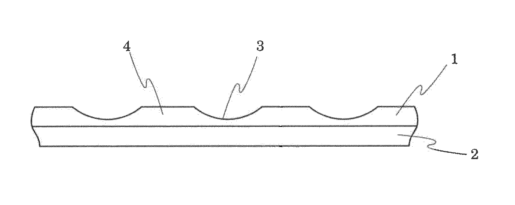
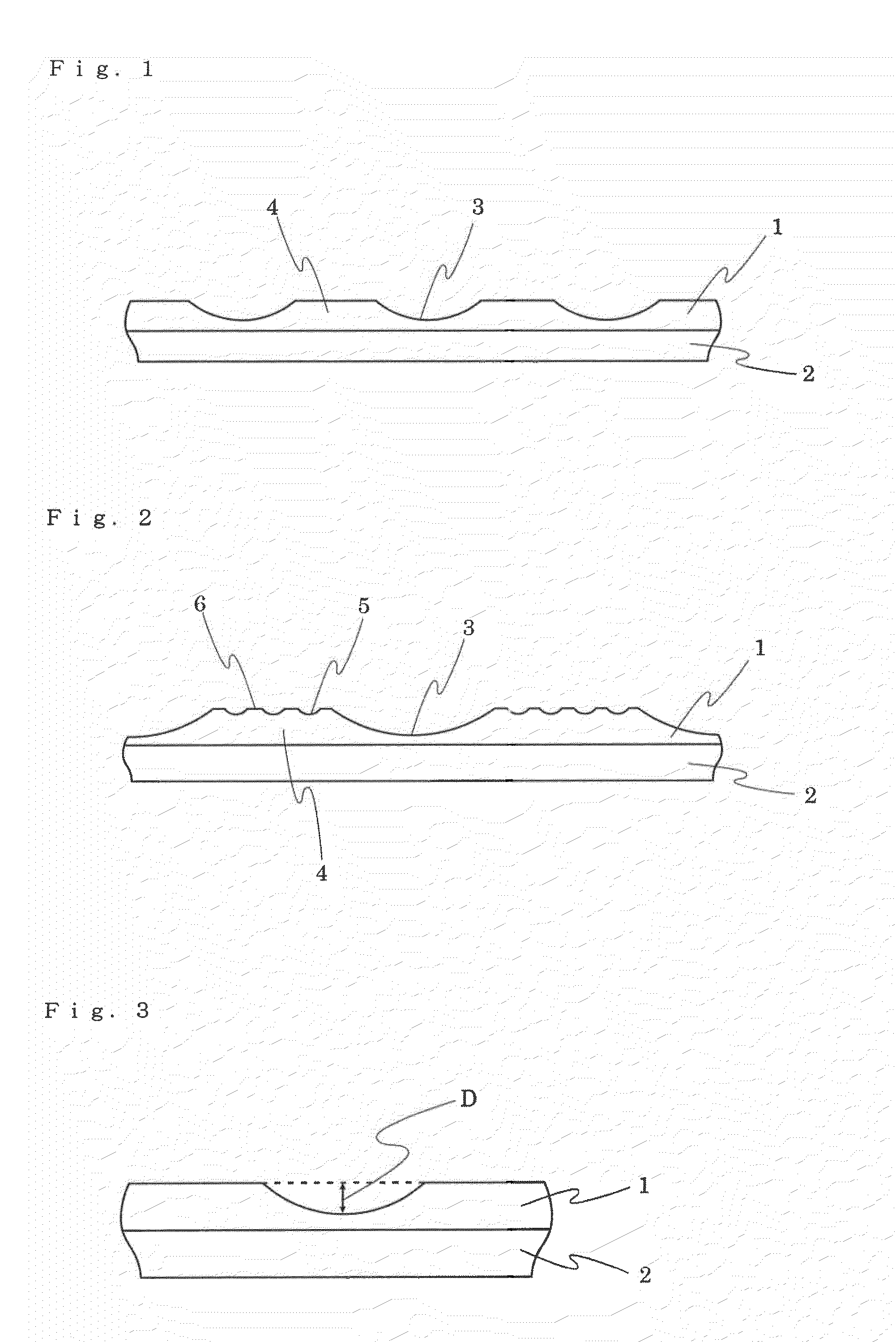
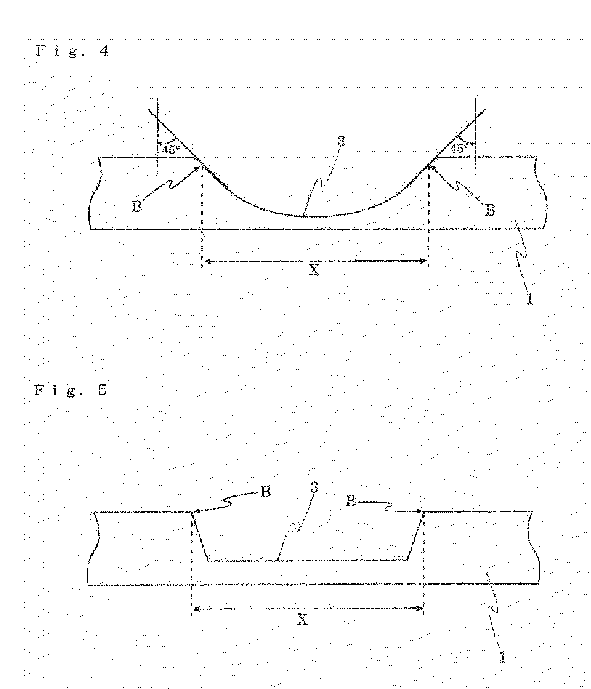
  • Sheet-like object for ball and ball
  • Sheet-like object for ball and ball
  • Sheet-like object for ball and ball

Examples


example 1

[0091](1) Nylon-6 (island component) and high-fluidity low-density polyethylene (sea component) were melt-spun into sea / island mix-spun fibers (sea component / island component ratio=50 / 50). The obtained fibers were drawn, crimped, and then cut into 51 mm-long staples having a fineness of 3.5 dtex. The staples were carded and formed into a web through a cross-lapping method to be laminated. A stack of webs was needle-punched at a needling density 980 P / cm2 by using single-barbed felt needles, to thereby obtain a nonwoven fabric having a mass per unit area of 450 g / m2. The nonwoven fabric was dried under heating, pressed to smooth its surface, and impregnated with a 13% dimethylformamide (hereinafter, referred to as “DMF”) solution of polyether-based polyurethane, followed by the coagulation of the impregnated polyurethane in an aqueous solution of DMF. Then, the nonwoven fabric was washed with hot water, and polyethylene in the fibers was extracted and removed by hot toluene, to there...

example 2

[0094](1) The same procedure of Example 1 was followed except that embossing was performed at a temperature of 170° C., a pressure of 10 kg / cm, and an emboss rate of 1 m / minute by using an emboss roller having pebbles of a truncated pyramid shape with a height of 0.5 mm and a vertical projected area of 3 mm2. The obtained pattern of valleys had almost the same depths between the discontinuous pebbles, and an average depth of 200 μm. The obtained pattern had almost the same vertical projected areas of valleys, that is, vertical projected areas of valleys from the upper surfaces which are perpendicular to the sheet surface for any valley, and an average vertical projected area of 2 mm2. Further, the obtained pattern of valleys had an average distance between the valleys of 2.5 mm, and the total area of the projected areas of the valleys accounted for 9% of the surface area of the cover layer.

[0095](2) A volleyball with the obtained sheet on the surface was produced, and the ball was e...

example 3

[0096](1) The same nonwoven fabric (1) of Example 1 was impregnated with a 13% dimethylformamide solution (100% modulus, 100 kg / cm2) of polyester-based polyurethane in which polyethylene propylene adipate, 4,4′-diphenylmethane diisocyanate, and ethylene glycol were copolymerized. Immediately after that, the resultant nonwoven fabric was coated with a 20% dimethylformamide solution (100% modulus, 40 kg / cm2) of polycarbonate-based polyurethane, which was composed of polyhexa carbonate glycol, polymethylene propylene adipate, and methylenediamine and in which n-hexane diisocyanate, 4,4′-diphenylmethane diisocyanate, and ethylene glycol were copolymerized. The resultant was coagulated in a coagulation bath at DMF / water ratio of 30 / 70 to form a porous structure. Then, polyethylene in fiber was extracted and removed by washing with hot water and hot toluene, yielding an artificial leather-like fibrous base material composed of a 6-nylon microfine fiber and a porous polyurethane.

[0097](2) ...


PUM


Abstract

Provided are: a sheet-like ball material including a fibrous base material, and an elastic polymer cover layer that is laminated on a surface of the fibrous base material, in which continuous pebbles and discontinuous valleys are formed on a surface of the cover layer, the valleys discontinuously formed are formed at average intervals of 0.5 to 3 mm, the valley has a depth of 50 to 500 μm, a vertical projected area of each valley is 1 to 5 mm2, and a total area of the vertical projected area of each valley accounts for 3 to 30% relative to a surface area of the elastic polymer cover layer; a ball used for volleyball or beach volleyball including the sheet-like ball material, which is excellent in the controllability for all types of ball plays such as tossing and serving in the smoothness of the attenuation degree in the ball speed of the ball during flight of the ball, and in the design, e.g., three-dimensional shape, which is not realized in a heretofore-existing ball, and also has a sufficient surface abrasion resistance; and a sheet-like ball material suitably used for such balls.

Description

TECHNICAL FIELD[0001]The present invention relates to a ball for any one of volleyball and beach volleyball. The present invention more specifically relates to a ball suitably used for volleyball and beach volleyball, which has not only excellent three-dimensional shape but also sufficient surface abrasion resistance, excellent cushioning property, and controllability at the time of tossing the ball, and a sheet-like material suitably used for such a ball.BACKGROUND ART[0002]Various properties are required for a ball such as volleyball and beach volleyball. For example, surface abrasion resistance at high level is required for a surface material subjected to repeated rubbing or collision with the ground, a floor, or the like. Further, in a case where a ball is controlled directly with a hand, soft cushioning property and controllability are required for reducing impact on fingertips and / or arms in touching the ball. Further, in recent years, even when the surface of a ball gets wet ...

Claims


Application Information

Patent Timeline
Patent Type & Authority Patents(United States)
IPC IPC(8): A63B41/08
CPCA63B41/08A63B43/00A63B2243/0095
Inventor ASHIDA, TETSUYAOGATA, KOKIYASUDA, YOSHIAKISAEKI, TAKETOSHI
Owner KURARAY CO LTD
Learn More