High temperature and pressure solids handling system

Active Publication Date: 2017-05-11
GAS TECH INST
View PDF0 Cites 3 Cited by
  • Summary
  • Abstract
  • Description
  • Claims
  • Application Information

AI Technical Summary

Benefits of technology

[0017]The present invention further provides a method for managing bottom ash discharge rate of a fluidized bed gasification reactor, wherein the

Problems solved by technology

It has always been challenging to manage the flow of high temperature and high pressure solids, such as the bottom ash discharged from a fluidized bed coal gasifier, which need to be cooled and depressurized.
However those devices are subject to severe wear and tear under the hostile environment of high temperature and pressure.
Those devices also lack operational reliability.
In addition to rapid deterioration of the cooling screw caused by the high temperature and high pressure environment, the cooling an

Method used


Image

  • High temperature and pressure solids handling system
  • High temperature and pressure solids handling system
  • High temperature and pressure solids handling system

Examples


examples

[0060]Gasifier Cold Model Discharge System Testing

[0061]The gasifier cold model discharge testing was conducted at the research laboratories of Particulate Solid Research, Inc. (PSRI) in Chicago, Ill.

[0062]a) Description of Equipment

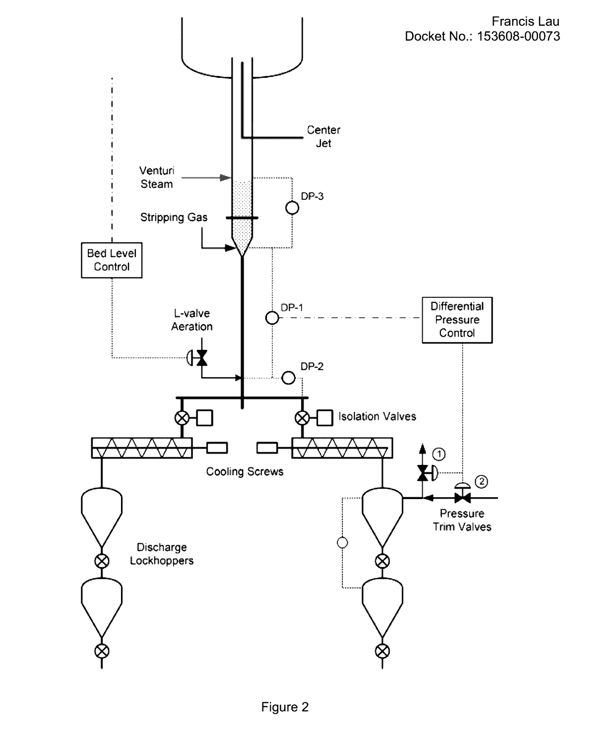
[0063]The cold flow testing was conducted at PSRI's research laboratories in Chicago, Ill., USA. An existing cold-flow test facility was modified to allow the desired testing. The primary vessel in the cold model was a 3-ft (0.9-m)-diameter fluidization column which housed the simulated gasifier bed. The vessel was approximately 20 feet (6 m) high which allowed large disengaging heights above the bed. The vessel was flanged near the bottom and the bottom flanged head contained a conical gas distributor and the venturi discharge test section. A drawing of the 10-in (25-cm)-diameter venturi section is shown in FIG. 2. Schematic drawings of the 8-in (20-cm) and 6-in (15-cm)-diameter venturis are shown in FIGS. 3 and 4, respectively. The venturi discharge co...


PUM


Abstract

A fluidized bed gasification system which comprises a fluidized bed gasification reactor having a bottom ash discharge outlet below the reactor, wherein an L-valve is used to control the rate of bottom ash discharge. The L-valve uses an aeration port located on distal side of the L-valve vertical pipe at a location that is above the center line of the horizontal pipe. Also provided are methods of controlling the bottom ash discharge as well the fluidized reaction bed height of the system.

Description

BACKGROUND OF THE INVENTION[0001]It has always been challenging to manage the flow of high temperature and high pressure solids, such as the bottom ash discharged from a fluidized bed coal gasifier, which need to be cooled and depressurized. Current systems typically use mechanical devices such as high temperature and / or high pressure valves and screws and other metering devices. However those devices are subject to severe wear and tear under the hostile environment of high temperature and pressure. Those devices also lack operational reliability. For example, a Synthetic Energy Systems® (SES) coal gasifier often uses a cooling screw, which needs to function both as a cooling device for the hot ash particles, and as a metering device to control solids flow rate. In addition to rapid deterioration of the cooling screw caused by the high temperature and high pressure environment, the cooling and metering functions of the cooling screw often are at odds with each other.[0002]Other exam...

Claims


Application Information

Patent Timeline
IPC IPC(8): C10J3/52C10J3/72C01B3/02C10J3/48
CPCC10J3/526C10J3/485C10J2300/093C01B3/02C10J3/723F23C10/24F23J1/00C10J3/523F23C10/26F23C10/30F23C2900/10008F23J2900/01006
Inventor LAU, FRANCIS SIKMING
Owner GAS TECH INST
Why Eureka
Try Eureka