Chain tensioner

a chain tensioner and chain technology, applied in the direction of belts/chains/gearings, mechanical equipment, belts/chains/gearings, etc., can solve the problems of inability to achieve the desired reaction force and damping characteristics corresponding to the rpm, inconvenient adjustment, and inability to adjust the valve opening pressure. , to achieve the effect of reducing the amount of oil flowing out of the system, reducing the rattling of the chain at the star

Active Publication Date: 2017-05-11
TSUBAKIMOTO CHAIN CO
View PDF0 Cites 17 Cited by
  • Summary
  • Abstract
  • Description
  • Claims
  • Application Information

AI Technical Summary

Benefits of technology

[0026]Also, the tensioner is configured such that the pressure is released by the first relief valve unit toward the side from which the oil is supplied, so that the amount of oil flowing out of the system can be reduced, and, since the pressure difference between the oil pressure chamber and the pressure relief side is smaller, the speed at which the first relief valve unit returns to its closed state can be increased.
[0027]Moreover, even when the first relief valve unit is activated before the oil supply is started, such as when starting the engine, the oil is circulated rather than flowing out of the system because of the structure in which the pressure is released toward the side from which the oil is supplied, and therefore, rattling of the chain at the start of the engine can be reduced.
[0028]According to the configuration set forth in claim 3, the plunger includes an oil reservoir chamber inside thereof, which is in fluid communication with an oil supply hole. The first relief valve unit is disposed between the oil reservoir chamber and the oil pressure chamber, with a relief valve seat thereof being oriented toward the oil pressure chamber. An oil circulation passage is formed between an outer circumference of a relief sleeve and an inner surface of the plunger for allowing released oil to circulate back to the oil reservoir chamber. When applied to chain tensioners of the type that has an oil reservoir chamber inside the plunger, the number of parts to be machined and the number of assembling steps are reduced, the amount of oil flowing out of the system is reduced, and damage to the check valve can be prevented, without having to increase the size of the chain tensioner.
[0029]Moreover, the oil can circulate back to the oil reservoir chamber when the check valve releases the oil, so that oil loss from the oil reservoir chamber can be reduced.
[0030]According to the configuration set forth in claim 4, the oil circulation passage includes an orifice that restricts the amount of oil. When the pressure of the oil pressure chamber has exceeded the valve opening pressure of the first relief valve unit but has not exceeded the valve opening pressure of the second relief valve unit, the pressure of the oil pressure chamber and the damping characteristics are maintained within a predetermined range because of the orifice. When the amount of oil has increased to surpass the effect of the orifice and to cause a further increase of pressure of the oil pressure chamber, the second relief valve unit opens, so that the chain tension during high speed rotation can be further lowered. Thus a correct level of pressure of the oil pressure chamber can be maintained for a wider range of engine oil pressure levels, and a desired reaction force corresponding to the rpm can be achieved.
[0031]According to the configuration set forth in claim 5, a bottom circulation passage is formed in the bottom part of the plunger bore. When the second relief valve unit opens at a high pressure of a predetermined level or more, the released oil will circulate back to the side where the oil was supplied from, so that the amount of oil flowing out of the system can be reduced.

Problems solved by technology

In the known chain tensioners including those of Japanese Patent Application Laid-open Nos. 2002-327810, 2011-226534, 2002-130401, 2002-235818, and 2006-125430, etc, there was a problem that it was very hard to set a correct valve opening pressure of the relief valve in relation to the engine oil pressure, so that a desired reaction force and damping characteristics corresponding to the rpm could not easily be achieved.
Too high a valve opening pressure would lead to noise and inappropriate tension and friction due to too much pressure being applied at low engine oil pressure, while too low a valve opening pressure would lead to inappropriate chain tension, incorrect tensioner behaviors, etc, due to looseness of the chain at high engine oil pressure.
On the other hand, the internal structure of the plunger is more complex and therefore the number of assembling steps is increased.

Method used


Image

  • Chain tensioner
  • Chain tensioner
  • Chain tensioner

Examples


embodiment 1

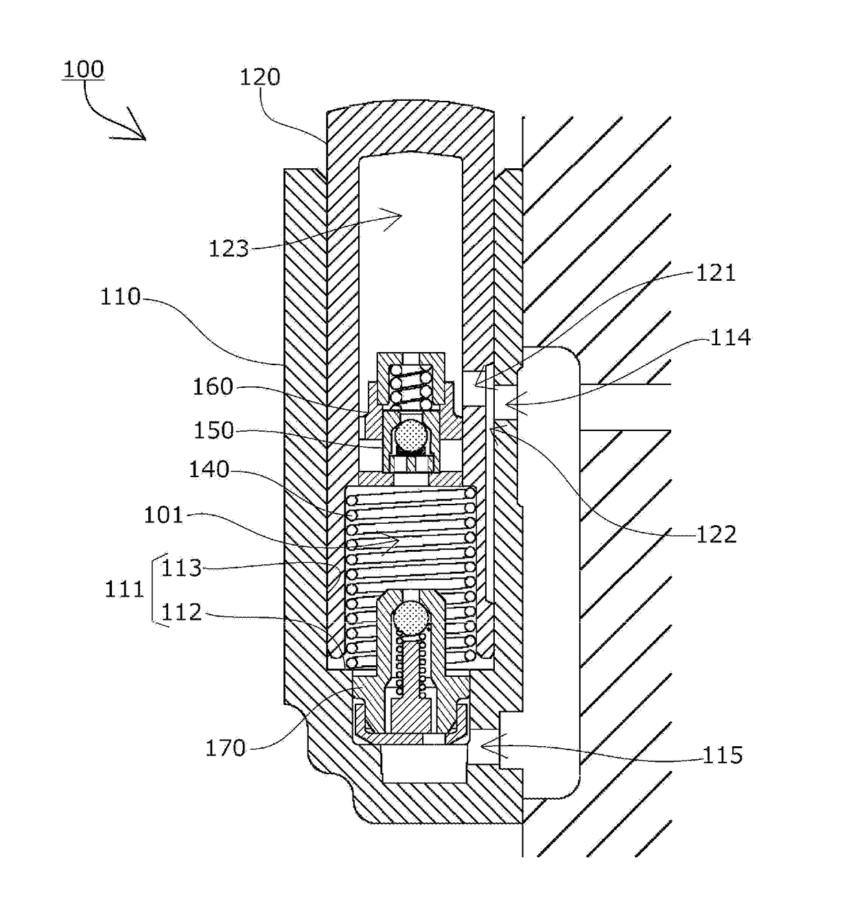
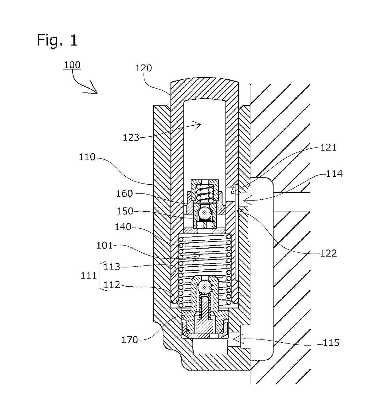
[0037]A chain tensioner 100 and a relief valve unit 160 according to one embodiment of the present invention will be described with reference to the drawings.

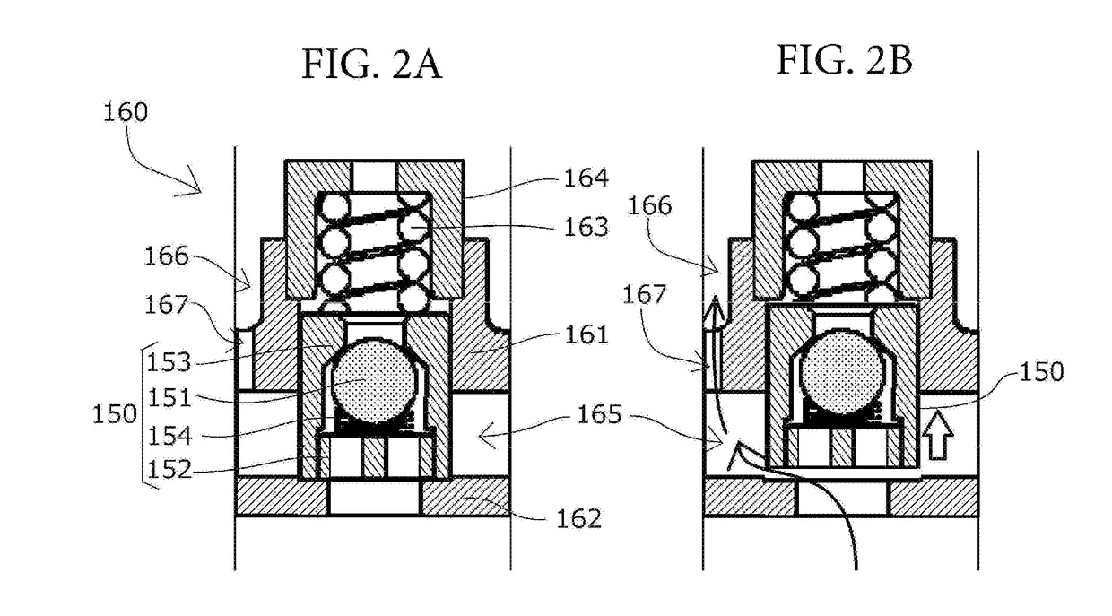
[0038]The chain tensioner 100 includes, as shown in FIG. 1, a plunger 120 that has an oil reservoir chamber 123 inside that is in fluid communication with an oil supply hole 114 via a supply passage 122 and a plunger supply hole 121. The first relief valve unit 160 is disposed between the oil reservoir chamber 123 and an oil pressure chamber 101, and an oil circulation passage 166 is formed between an outer circumference of a relief sleeve 161 of the first relief valve unit 160 and an inner surface of the plunger 120 for allowing released oil to circulate back to the oil reservoir chamber 123.

[0039]A coil spring 140, which is means for urging the plunger 120 in a projecting direction, is received on one end thereof by a bottom part 112 of the plunger bore 111 of the tensioner body 110 to apply a pressing force. The oil pressure...


PUM


Abstract

To provide a chain tensioner that can maintain the pressure of the oil pressure chamber at a correct level to achieve a desired reaction force and damping characteristics corresponding to the rpm, and enable a reduction in the number of parts to be machined and the number of assembling steps; reduce the amount of oil flowing out of the system; and prevent damage to the check valve, without causing an increase in size of the chain tensioner. The chain tensioner includes a check valve unit 150 that stops reverse flow of oil flowing into an oil pressure chamber 101, and a first relief valve unit 160 and a second relief valve unit 170 that release oil when the pressure reaches or exceeds a predetermined high level. The second relief valve unit 170 has a higher valve opening pressure than that of the first relief valve unit 160.

Description

BACKGROUND OF THE INVENTION[0001]1. Field of the Invention[0002]The present invention relates to a chain tensioner that includes a tensioner body having a cylindrical plunger bore with one open end, a cylindrical plunger slidably inserted in the plunger bore, and biasing means accommodated inside an oil pressure chamber formed between the plunger bore and the plunger such as to freely expand and contract and to urge the plunger in a projecting direction, and that maintains appropriate tension of a chain.[0003]2. Description of the Related Art[0004]It has been common practice to use a chain tensioner for maintaining appropriate tension of a chain. For example, a chain guide mechanism has been known, which slidably guides, by means of a guide shoe, a transmission chain such as an endless roller chain passing over respective sprockets of a crankshaft and a cam shaft inside an engine room, and which uses a chain tensioner to press a pivoting chain guide having the guide shoe to maintain...

Claims


Application Information

Patent Timeline
Patent Type & Authority Applications(United States)
IPC IPC(8): F16H7/08
CPCF16H7/0848F16H2007/0859F16H2007/0893F16H2007/0872F16H2007/0814F16H7/08F16H2007/0806
Inventor KUREMATSU, YUJI
Owner TSUBAKIMOTO CHAIN CO
Why Eureka
Try Eureka