Radar measuring method

a technology of measuring method and frequency difference, applied in the direction of measuring device, using reradiation, instruments, etc., can solve the problems of not allowing the determination of distance, velocity cannot be exactly calculated, and only estimated, so as to achieve accurate estimation of relative velocity

Active Publication Date: 2017-05-11
ROBERT BOSCH GMBH
View PDF7 Cites 10 Cited by
  • Summary
  • Abstract
  • Description
  • Claims
  • Application Information

AI Technical Summary

Benefits of technology

[0008]The object of the present invention is to provide a method for determining a relative

Problems solved by technology

A measurement of the frequency difference on a single ramp therefore does not yet permit a determination of the distance and the relative velocity, but instead supplies only a linear relationship between those vari

Method used


Image

  • Radar measuring method
  • Radar measuring method
  • Radar measuring method

Examples


Embodiment Construction

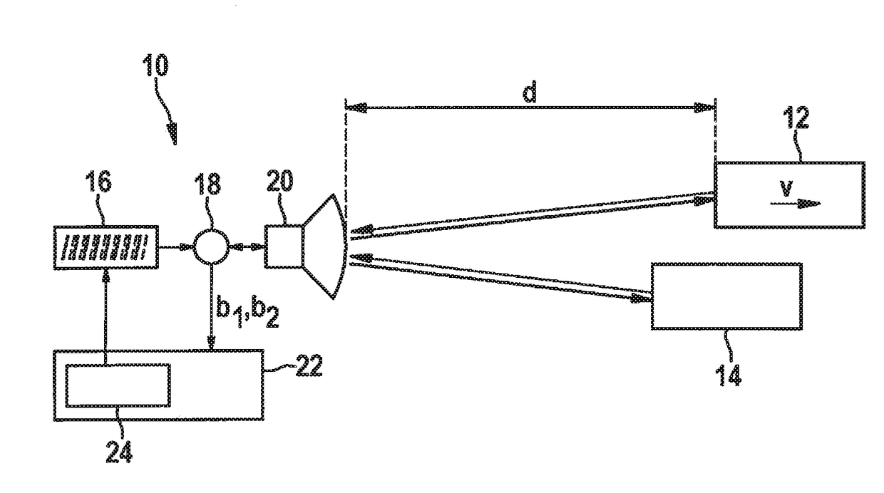
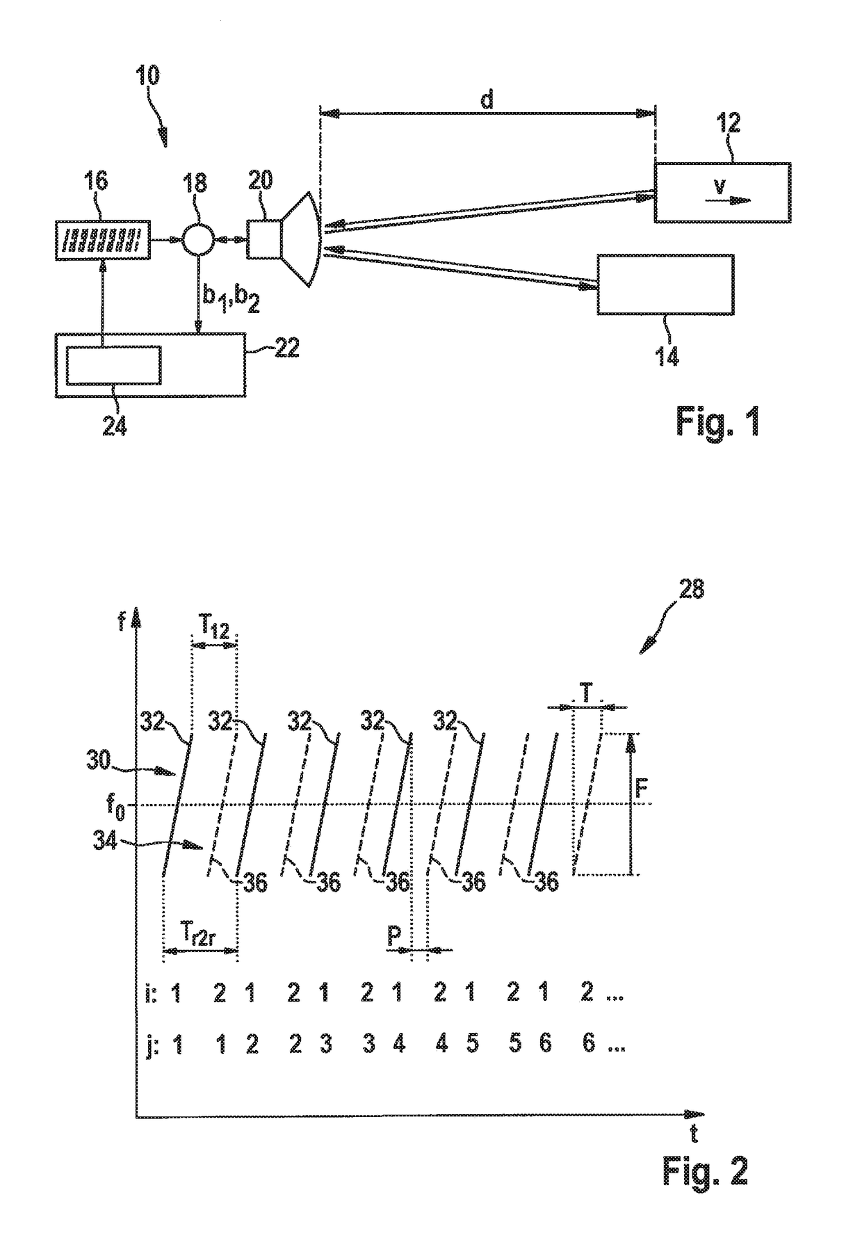
[0044]FIG. 1 is a simplified block diagram depicting an FMCW radar sensor 10 that, for example, is installed at the front in a motor vehicle and serves to measure distances d and relative velocities v of objects 12, 14, for example of preceding vehicles. Radar sensor 10 has a voltage-controlled oscillator 16 that supplies a frequency-modulated transmitted signal via a mixer 18 to a transmission and reception device 20 from which the signal is emitted toward objects 12, 14. The signal reflected at the objects is received by transmission and reception device 20 and mixed in mixer 18 with a component of the transmitted signal. A baseband signal b is thereby obtained, and is further evaluated in an electronic evaluation and control device 22. Control and evaluation device 22 contains a control section 24 that controls the functioning of oscillator 16. The frequency of the transmitted signal supplied by the oscillator is modulated within a radar measurement with sequences of rising or fa...


PUM


Abstract

An FMCW radar sensor and method for determining a relative velocity of a radar target, in which an FMCW radar measurement is performed with a transmitted signal whose modulation pattern encompasses mutually temporally interleaved sequences of ramps; from the baseband signals a two-dimensional spectrum is calculated separately for each of the sequences; from a position of a peak in at least one two-dimensional spectrum of the baseband signals, values for the relative velocity of a radar target which are periodic with a predetermined velocity period are determined; a phase relationship between spectral values that are obtained respectively at the same position in the separately calculated two-dimensional spectra is checked for agreement with phase relationships expected for several of the determined periodic values of the relative velocity; and based thereon, an estimated value for the relative velocity of the target is selected from the determined periodic values of the relative velocity.

Description

FIELD[0001]The present invention relates to a method for determining a relative velocity of a radar target.[0002]The present invention further relates to a radar sensor, in particular for motor vehicles, that is configured to carry out that method.BACKGROUND INFORMATION[0003]In motor vehicles, FMCW radar sensors are used to detect the traffic environment, in particular to localize other vehicles. The localization results can be used for a variety of assistance functions, for example for automatic separation control, automatic collision warning, or also automatic triggering of an emergency braking procedure in the case of an acute risk of collision.[0004]In frequency modulated continuous wave (FMCW) radar sensors, a transmitted signal whose transmission frequency is modulated in ramp-shaped fashion is used, the signal being transmitted continuously during the course of the ramp. A baseband signal is generated from a received signal by mixing with the transmitted signal, and is sample...

Claims


Application Information

Patent Timeline
IPC IPC(8): G01S13/58G01S13/02G01S13/931
CPCG01S13/583G01S13/931G01S13/0209G01S7/354G01S13/34G01S13/343G01S7/356
Inventor SCHOOR, MICHAELLOESCH, BENEDIKT
Owner ROBERT BOSCH GMBH
Why Eureka
Try Eureka