Semiconductor device and manufacturing method thereof

a semiconductor device and manufacturing method technology, applied in the field of semiconductor devices, can solve the problem of unnecessarily large overall thickness of the completed semiconductor devi

Inactive Publication Date: 2017-05-11
AMKOR TECH SINGAPORE HLDG PTE LTD
View PDF2 Cites 14 Cited by
  • Summary
  • Abstract
  • Description
  • Claims
  • Application Information

AI Technical Summary

Benefits of technology

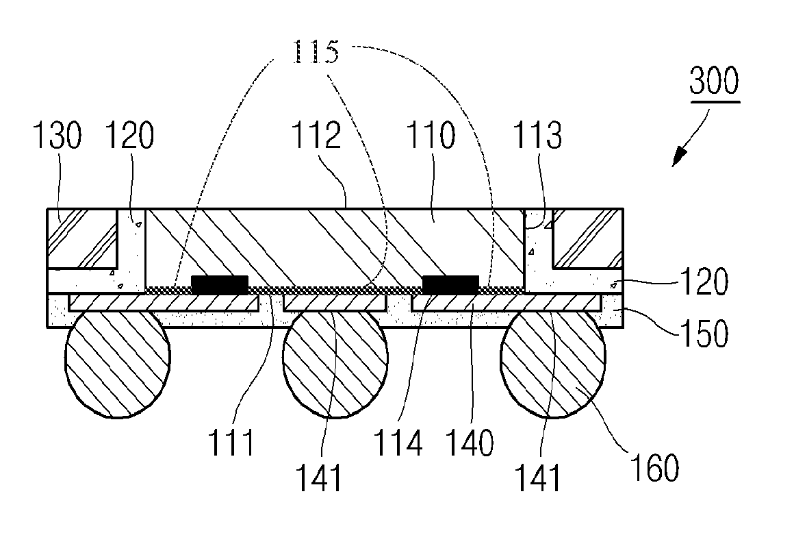
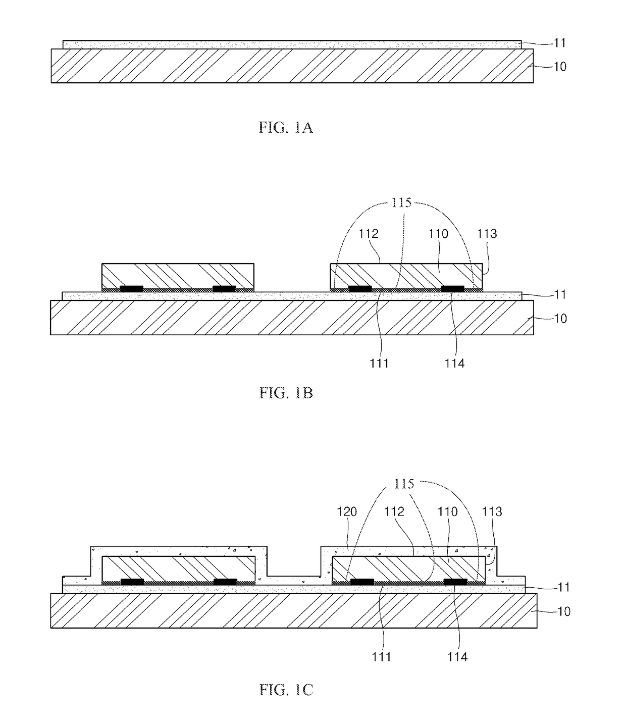
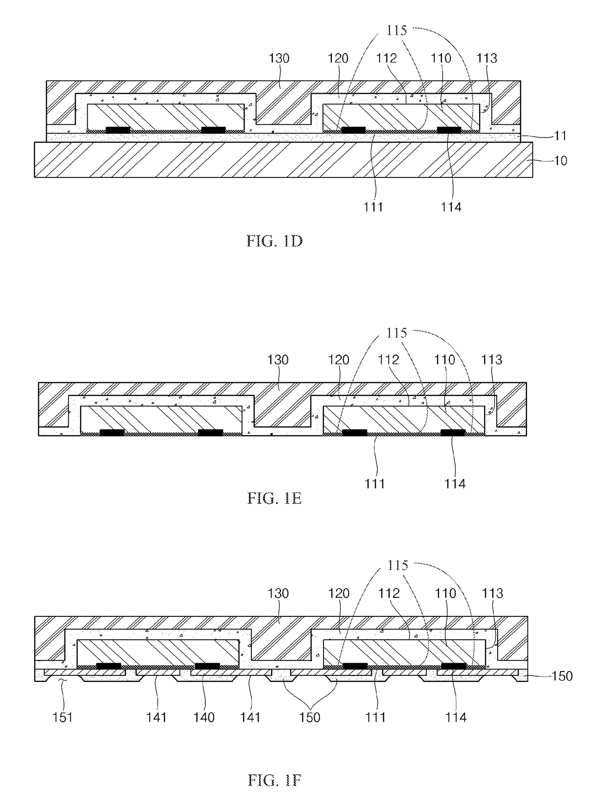
[0014]Various aspects of the present disclosure provide a semiconductor device and a manufacturing method thereof, which can reduce a number of manufacturing processes and / or can reduce a thickness of the semiconductor device. As a non-limiting example, various aspects of this disclosure provide for the elimination of process steps and / or a reduction in package size based on dielectric layer characteristics.

Problems solved by technology

In addition, since the dielectric layer may be formed on the semiconductor die and on the surface of the encapsulant layer, the overall thickness of the completed semiconductor device may be unnecessarily large.

Method used


Image

  • Semiconductor device and manufacturing method thereof
  • Semiconductor device and manufacturing method thereof
  • Semiconductor device and manufacturing method thereof

Examples


Embodiment Construction

[0015]The following discussion presents various aspects of the present disclosure by providing various examples thereof. Such examples are non-limiting, and thus the scope of various aspects of the present disclosure should not necessarily be limited by any particular characteristics of the provided examples. In the following discussion, the phrases “for example,”“e.g.,” and “exemplary” are non-limiting and are generally synonymous with “by way of example and not limitation,”“for example and not limitation,” and the like.

[0016]As utilized herein, “and / or” means any one or more of the items in the list joined by “and / or”. As an example, “x and / or y” means any element of the three-element set {(x), (y), (x, y)}. In other words, “x and / or y” means “one or both of x and y.” As another example, “x, y, and / or z” means any element of the seven-element set {(x), (y), (z), (x, y), (x, z), (y, z), (x, y, z)}. In other words, “x, y and / or z” means “one or more of x, y, and z.”

[0017]The termino...


PUM


Abstract

A semiconductor device and a manufacturing method thereof, which can reduce a number of manufacturing processes and / or can reduce a thickness of the semiconductor device. As a non-limiting example, various aspects of this disclosure provide for the elimination process steps and / or a reduction in package size based on dielectric layer characteristics.

Description

CROSS-REFERENCE TO RELATED APPLICATIONS / INCORPORATION BY REFERENCE[0001][Not Applicable].FEDERALLY SPONSORED RESEARCH OR DEVELOPMENT[0002][Not Applicable]SEQUENCE LISTING[0003][Not Applicable]MICROFICHE / COPYRIGHT REFERENCE[0004][Not Applicable]BACKGROUND[0005]Field[0006]The present invention relates to a semiconductor device and a manufacturing method thereof.[0007]Description of the Related Art[0008]In general, a wafer level chip size package and / or other package types may comprise a redistribution layer, which is formed on a semiconductor die and a surface of an encapsulant layer. Since it may be difficult to form the redistribution layer directly on the surface of the encapsulant layer, a dielectric layer (e.g., a passivation layer) may be first formed on the semiconductor die and on the surface of the encapsulant layer, followed by formation of the redistribution layer on the dielectric layer.[0009]In instances where the dielectric layer is formed to cover bond pads, photo / etch ...

Claims


Application Information

Patent Timeline
Patent Type & Authority Applications(United States)
IPC IPC(8): H01L23/00H01L21/56H01L23/31
CPCH01L24/05H01L23/3157H01L2224/0231H01L2224/0401H01L2224/02371H01L21/568H01L23/3171H01L23/3185H01L23/367H01L23/3135H01L24/19H01L24/20H01L24/96H01L24/97H01L2224/04105H01L2224/12105H01L2924/18162B66F9/18B66F9/184B66F9/19
Inventor KIM, DO HYUNGCHUNG, YOUNG SUKHAN, SEUNG CHULPARK, JUNG SOO
Owner AMKOR TECH SINGAPORE HLDG PTE LTD
Why Eureka
Try Eureka