Transmitting device for transmitting electrical signals from at least one galvanic cell to at least one electronic evaluating unit

a technology of electrical signals and transmission devices, which is applied in secondary cells, battery services/maintenance, cell components, etc., can solve the problems of low robustness, damage to bonding wire connections, and even cracking of bonding wire connections

Active Publication Date: 2017-05-11
ROBERT BOSCH GMBH
View PDF2 Cites 9 Cited by
  • Summary
  • Abstract
  • Description
  • Claims
  • Application Information

AI Technical Summary

Benefits of technology

[0005]It is therefore the object of the present invention to at least partly eliminate the disadvantages described above for an apparatus for ascertaining the voltage values and / or temperature values of a cell, particularly a galvanic cell. In particular, it is the object of the present invention to provide a transmission apparatus for transmitting electrical signals from at least one galvanic cell to at least one electronic evaluation unit, by means of which individual values or data, such as the cell voltage or the temperature of the cell, can be captured and transmitted from the individual cell to the electronic evaluation unit in a simple and inexpensive manner, the transmission apparatus itself being intended to be arrangeable in a space-saving manner and to be flexibly deformable with zero damage, in order also to allow the individual cells to move among one another.

Problems solved by technology

Particularly the bonding wires serving as voltage taps have a very thin cross section, however, and accordingly, disadvantageously, low robustness.
This means that even if the individual cells move just slightly among one another within the module complex, the loads acting on the bonding wires can cause damage to the bonding wire connections on account of the tensile, compressive and flexural forces, as a result of which said bonding wire connections even crack.
A further disadvantage, in the case of the connection of the fundamentally known voltage taps in the form of lines or bonding wire connections, can be regarded as the resultant high contact resistance between the voltage taps and the cell connector, which arises not only as a result of the voltage taps needing to be welded or screwed onto the cell connector, for example, but also from the fact that the weld joints or screw joints can detach or loosen, owing to the movement of the individual cells in the battery pack among one another.
An increase in a contact resistance from a tap to the cell connector can also disadvantageously lead to faults in the electronics as a result of the heat generation from the voltage tap.
Additionally, the increase in the contact resistance from a tap to the cell connector can also lead to a loss of voltage.
It has also been found that the cell terminals are difficult to bond insofar as the terminals move to a minimal degree.
The machine exerts slight pressure on the cell terminals in order to firmly weld the bond by means of friction welding, this movement being transferred to the terminal, as a result of which the latter moves too greatly.
Therefore, bonding is very difficult depending on the cell type and depending on the mechanical structure of the cell, this also having been shown in latest tests.
Therefore, even the arrangement of a corresponding contact-connection unit encounters the risk of the individual components of the contact-connection unit being displaced among one another in the event of movement between the individual cells of the module complex of a battery or of a storage battery.
This may at least intermittently and / or partly break a contact connection, so that individual values and particularly voltage values or temperature values can no longer be captured from the galvanic cell and therefore also no longer transmitted to the evaluation unit.

Method used


Image

  • Transmitting device for transmitting electrical signals from at least one galvanic cell to at least one electronic evaluating unit
  • Transmitting device for transmitting electrical signals from at least one galvanic cell to at least one electronic evaluating unit
  • Transmitting device for transmitting electrical signals from at least one galvanic cell to at least one electronic evaluating unit

Examples


Embodiment Construction

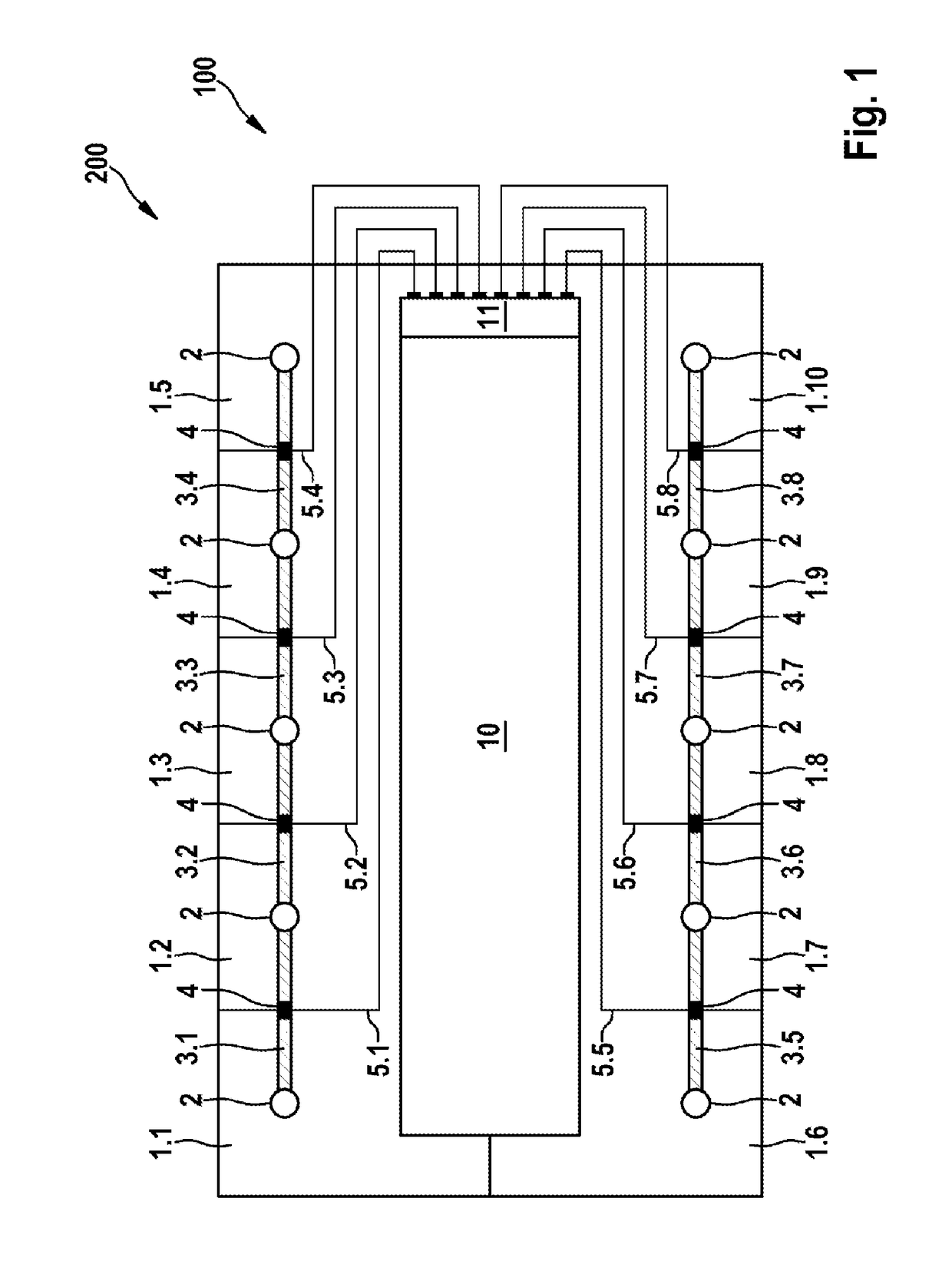
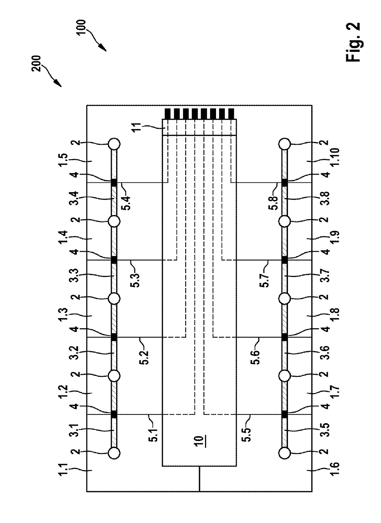
[0027]Elements having the same function and action are each provided with the same reference symbols in FIGS. 1 and 2.

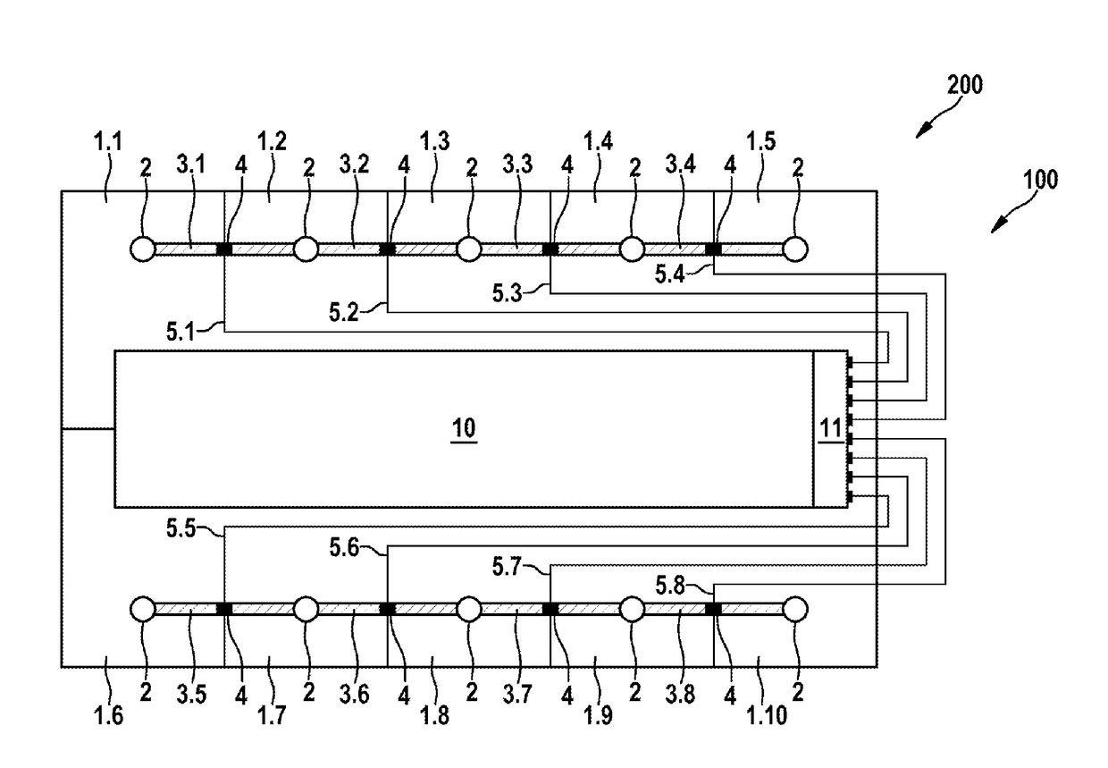
[0028]FIG. 1 shows an embodiment of a rechargeable energy storage unit 200 that has a plurality of galvanic cells 1.1 to 1.10 that are connected up to one another in the form of a cell module and particularly a battery cell module or storage battery cell module. Each galvanic cell 1.1 to 1.10 has at least two terminals 2, only one terminal 2 of each galvanic cell 1.1 to 1.10 being visible in FIG. 1. The reason for this is that particularly the electronic evaluation unit 10 is arranged above the individual galvanic cells 1.1 to 1.10, and consequently conceals one of the two terminals 2 of each galvanic cell 1.1 to 1.10. The galvanic cells 1.1 to 1.10 are connected up to one another by appropriate cell connecting elements 3.1 to 3.8 in order to transmit electric power to one another. The cell connecting elements 3.1 to 3.8 extend between the terminals 2 of the individu...


PUM

PropertyMeasurementUnit
distanceaaaaaaaaaa
electricaaaaaaaaaa
electricalaaaaaaaaaa

Abstract

The invention relates to a transmitting device for transmitting electrical signals from at least one galvanic cell to at least one electronic evaluating unit, wherein the transmitting device has at least one cell connection element for electrically connecting at least a first galvanic cell to a second galvanic cell and has a flat cable arranged directly on the cell connection element, wherein the flat cable extends from the cell connection element to an electronic evaluating unit for evaluating the electrical signals. The invention further relates to a rechargeable energy storage unit at least for storing electrical energy, comprising at least two galvanic cells electrically connected to each other and a transmitting device, and to the use of at least one flat cable for transmitting electrical signals from at least one galvanic cell to at least one electronic evaluating unit.

Description

BACKGROUND OF THE INVENTION[0001]The present invention relates to a transmission apparatus for transmitting electrical signals from at least one galvanic cell to at least one electronic evaluation unit. Further, the present invention relates to a rechargeable energy storage unit and to the use of at least one ribbon line for transmitting electrical signals.[0002]It is fundamentally known that batteries and storage batteries, such as particularly lithium ion batteries, consist of at least one battery cell module or of a plurality of battery cell modules. A single battery cell module advantageously has a multiplicity of single battery cells that are connected up to one another to form a battery cell module or battery pack. It is thus conceivable for the individual battery cells or cells to be connected up to one another in the form of the series circuit or in the form of the parallel circuit. In the case of the series circuit, the individual cells are connected in succession, the conn...

Claims


Application Information

Patent Timeline
Patent Type & Authority Applications(United States)
IPC IPC(8): H01M10/42H01M2/10H01M10/48H01M50/209
CPCH01M10/425H01M10/482H01M2220/20H01M2010/4278H01M2/1077H01M50/209Y02E60/10
Inventor SCHUETZ, JONAS
Owner ROBERT BOSCH GMBH
Why Eureka
Try Eureka