Contactless power receiver, contactless power feeder, and contactless power transmission system provided with same

a technology of contactless power transmission and transmission system, which is applied in the direction of telephone set construction, substation equipment, transportation and packaging, etc., can solve the problem of greater than 1 kw of consumable power, and achieve the effect of accurate communication

Active Publication Date: 2017-05-11
PANASONIC INTELLECTUAL PROPERTY MANAGEMENT CO LTD
View PDF6 Cites 24 Cited by
  • Summary
  • Abstract
  • Description
  • Claims
  • Application Information

AI Technical Summary

Benefits of technology

[0024]In a technology of the related art described in NPL 1, power to be transmitted is limited to be less than or equal to 5 W, and thus, it is easy to perform communication by superimposing data on the power to be transmitted. For this reason, a coil for contactless power transmission and a coil for communication are communized on both of a power feeding side and a power reception side, and at all times, it is possible to simultaneously perform power transmission and data communication.
[0031]In bidirectional communication, it is reasonable that the same wireless resource is used by being subjected to time division. In a case of a contactless power transmission system, the bidirectional communication is mainly performed in the vicinity of the zero cross point of the power to be transmitted, and thus, in a case where higher power is transmitted, the data communication is easily affected by the noise.
[0032]The present disclosure has been made in order to solve the problems of the related art, and an object thereof is to provide a contactless power feeder and a contactless power receiver in which it is possible to accurately perform communication having a large amount of information between the contactless power receiver and the contactless power feeder without being affected by a noise due to contactless power transmission.
[0035]According to the aspects described above, it is possible to accurately perform communication having a large amount of information between the contactless power receiver and the contactless power feeder without being affected by a noise due to contactless power transmission.

Problems solved by technology

However, in the technology of the related art described in PTL 1, there is a case where consumed power is greater than 1 kW.

Method used


Image

  • Contactless power receiver, contactless power feeder, and contactless power transmission system provided with same
  • Contactless power receiver, contactless power feeder, and contactless power transmission system provided with same
  • Contactless power receiver, contactless power feeder, and contactless power transmission system provided with same

Examples


exemplary embodiment 1

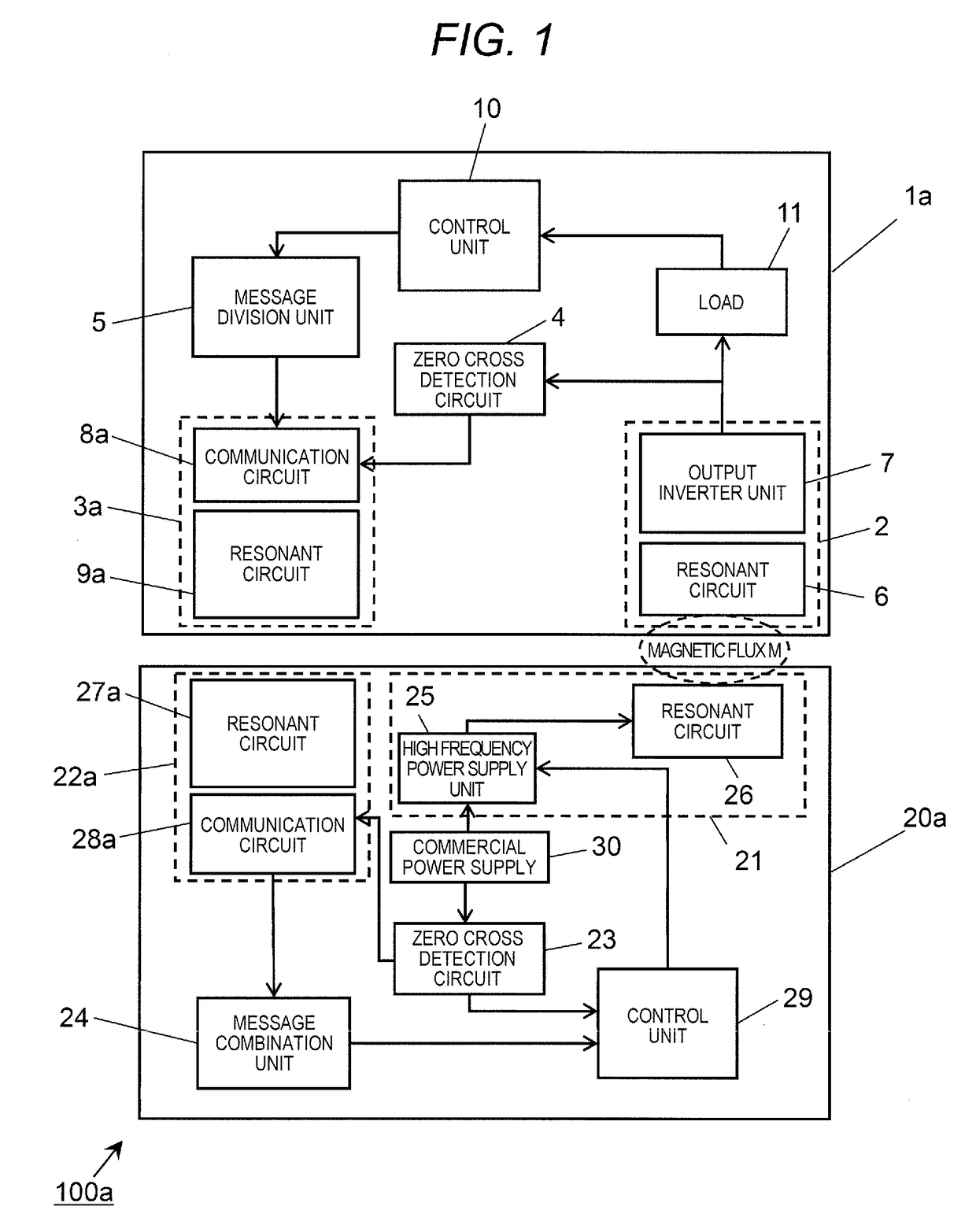
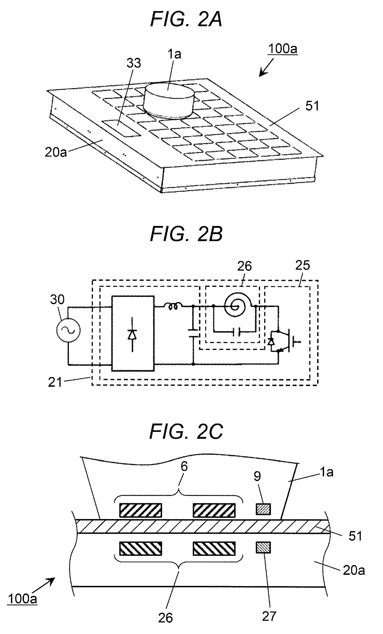
[0099]FIG. 1 is a block configuration diagram of contactless power transmission system 100a according to Exemplary Embodiment 1 of the present disclosure. FIG. 2A is a perspective view illustrating an appearance of contactless power feeder 20a according to this exemplary embodiment. FIG. 2B is a block configuration diagram illustrating a circuit configuration for driving each dielectric heating coil disposed in contactless power feeder 20a according to this exemplary embodiment.

[0100]In FIG. 1, contactless power receiver 1a, for example, is a juicer, a blender, or a jar pot. Load 11, for example, is a motor used for a juicer and a blender, or a heater used for a jar pot.

[0101]A power feeder embedded in a counter top of a kitchen, and a power feeder which is used as an induction heating cooking device are assumed as contactless power feeder 20a. Contactless power receiver 1a is independent from contactless power feeder 20a, and is used by being mounted on contactless power feeder 20a...

modification example of exemplary embodiment 1

[0153]FIG. 8 is a block configuration diagram of contactless power transmission system 100b according to a modification example of Exemplary Embodiment 1. In the drawings for illustrating this modification example, the same reference numerals are applied to the identical or corresponding portions to those of the drawings described above, and the detailed description thereof will be omitted.

[0154]As illustrated in FIG. 8, contactless power transmission system 100b is different from contactless power transmission system 100a illustrated in FIG. 1 in the following points. Contactless power receiver 1b does not include zero cross detection circuit 4, but includes power reception communication unit 3b instead of communication unit 3a. Contactless power feeder 20b includes power feeding communication unit 22b instead of communication unit 22a.

[0155]Power reception communication unit 3b includes resonant circuit 9b including a power reception coil, and power supply circuit 8b. Power feedi...

exemplary embodiment 2

[0165]FIG. 10 is a block configuration diagram of contactless power transmission system 100c according to Exemplary Embodiment 2 of the present disclosure. FIG. 11 is a diagram illustrating an example of a timing chart of each signal and a format of a communication packet in contactless power transmission system 100c. In the drawings for illustrating this exemplary embodiment, the same reference numerals are applied to the identical or corresponding portions to those of the drawings described above, and the detailed description thereof will be omitted.

[0166]As illustrated in FIG. 10, contactless power transmission system 100c is different from contactless power transmission system 100a illustrated in FIG. 1 in the following points.

[0167]Contactless power receiver 1c does not include message division unit 5, but includes communication unit 3c including communication circuit 8c and resonant circuit 9c instead of communication unit 3a. Contactless power feeder 20c does not include mess...


PUM


Abstract

Contactless power receiver 1a includes power reception unit having a contactless power reception function using electromagnetic induction; communication unit separately transmitting a plurality of data items in the vicinity of a zero cross point of an alternating current voltage from commercial power supply; and power reception side message division unit dividing a transmission message into a plurality of data items. Contactless power feeder includes power feeding unit having a contactless power feeding function using electromagnetic induction; communication unit separately receiving a plurality of data items in the vicinity of a zero cross point of an alternating current voltage from commercial power supply; and power feeding side message combination unit generating a reception message by combining a plurality of data items. Each of the plurality of data items which are divided by power reception side message division unit and are combined by power feeding side message combination unit has a size transmittable in the vicinity of the zero cross point. According to this configuration, it is possible to accurately perform communication having a large amount of information without being affected by a noise due to contactless power transmission.

Description

TECHNICAL FIELD[0001]The present disclosure relates to a contactless power transmission system for consumer electronics and the like.BACKGROUND ART[0002]FIG. 30 is a block configuration diagram of a contactless power transmission system of the related art described in PTL 1.[0003]As illustrated in FIG. 30, in PTL 1, contactless power receiver 401 is disclosed in which input of a command and output of information with respect to contactless power feeder 420 are performed in order to improve usability and reliability of contactless power receiver 401.[0004]Contactless power receiver 401 includes resonant circuit for power reception 405a which becomes a power reception unit for receiving power fed from contactless power feeder 420 over the wireless on the basis of a change in a magnetic flux generated at the time of operating contactless power feeder 420, and resonant circuit 405b performing bidirectional communication of a communication signal with respect to contactless power feeder ...

Claims


Application Information

Patent Timeline
Patent Type & Authority Applications(United States)
IPC IPC(8): H02J50/12H02J50/80H04M1/02H02J7/02H04M1/72412
CPCH02J50/12H04M1/0202H02J50/80H02J7/025H04M1/72412
Inventor TOMINAGA, HIROSHIKUROBE, AKIOOGAWA, KEIJI
Owner PANASONIC INTELLECTUAL PROPERTY MANAGEMENT CO LTD
Why Eureka
Try Eureka