
Side Loading Articulating Laryngeal Access System

Active Publication Date: 2017-05-18
SANOVAS
View PDF7 Cites 9 Cited by
  • Summary
  • Abstract
  • Description
  • Claims
  • Application Information

AI Technical Summary

Benefits of technology

The patent is about an improved system for giving access to the larynx (the part of the throat where air flows into the windpipe) for the purpose of intubation (adding a tube to the patient's airway for breathing during medical procedures). The system is designed to be easily adjustable for different patients, and to be assembled quickly and easily in case of emergency situations. It also provides a better field of view for quicker intubation and reduces the risk of injury to the patient. Additionally, it allows better control and efficiency for the medical professionals performing the intubation.

Problems solved by technology

The insertion of the endotracheal tube often involves serious risks, such as damage to the vocal cords and a prolonged intubation procedure in which the patients breathing is stopped, but oxygen is not yet delivered to the patient as the tube has not yet been inserted.
Some of the difficulties that persons performing endotracheal intubation encounter include the restriction of view as the tube is inserted, variations in the anatomy of the patients, an uncomfortable and unnatural position of the person performing the procedure while holding the instrument, and the necessity for rapid intubation.
However, the known imaging intubation devices still suffer from a number of disadvantages and drawbacks.
However, different types of patients often have different anatomies and it may be challenging to use the rigid blade for different types of patients because the blade's shape cannot be easily adjusted to fit the anatomy of a particular patient, particularly at the distal end of the blade.
Additionally, because the current systems require separate insertion of the laryngeal blade and the endotracheal tube, they require significant time to set up and to insert into the patient.
In emergent situations this delay could be hazardous, if not deadly.
Another major problem with current systems is the limited field of view, requiring more time for the user to intubate the patient.
Typically, the imaging device is positioned at a distal tip of the device body which only provides a limited view of the surrounding tissue, even if the distal tip is capable of being angled to a certain degree.

Method used


Image

  • Side Loading Articulating Laryngeal Access System
  • Side Loading Articulating Laryngeal Access System
  • Side Loading Articulating Laryngeal Access System

Examples


Embodiment Construction

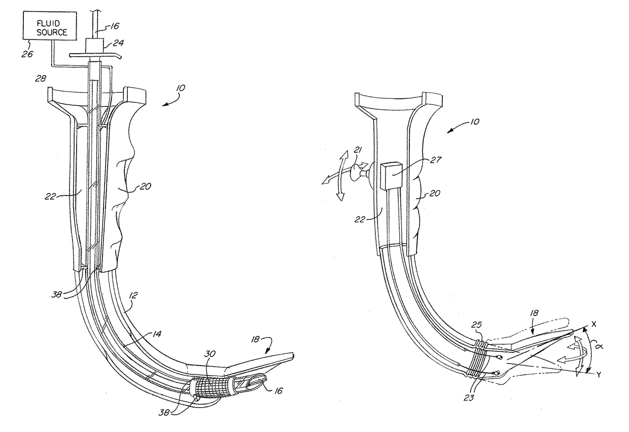
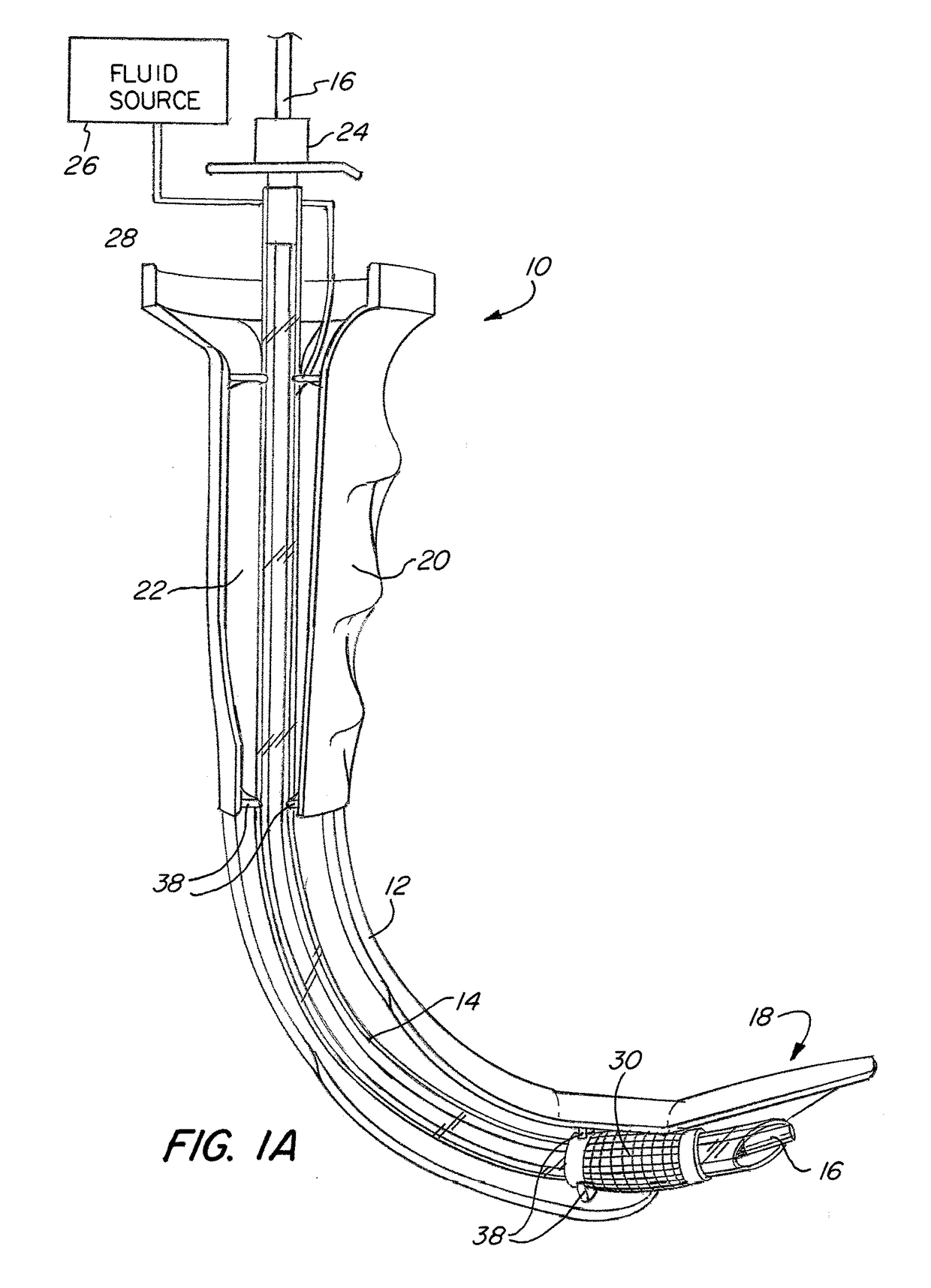
[0035]The basic components of one embodiment of a laryngeal access system in accordance with the invention are illustrated in FIG. 1A. As used in the description, the terms “top,”“bottom,”“above,”“below,”“over,”“under,”“above,”“beneath,”“on top,”“underneath,”“up,”“down,”“upper,”“lower,”“front,”“rear,”“back,”“forward” and “backward” refer to the objects referenced when in the orientation illustrated in the drawings, which orientation is not necessary for achieving the objects of the invention.

[0036]As shown in FIG. 1A, the laryngeal access system (10) includes a laryngeal blade or cannula (12). In some embodiments, the blade (12) is made with any suitable rigid or semi-rigid material, such as, e.g., metal or polymer, and is pre-shaped to correspond to the anatomy of a person's throat and trachea. In other embodiments, the blade (12) may be made with malleable material, such that the blade can be bent into a desired shape right before the intubation procedure to more precisely corresp...


PUM


Abstract

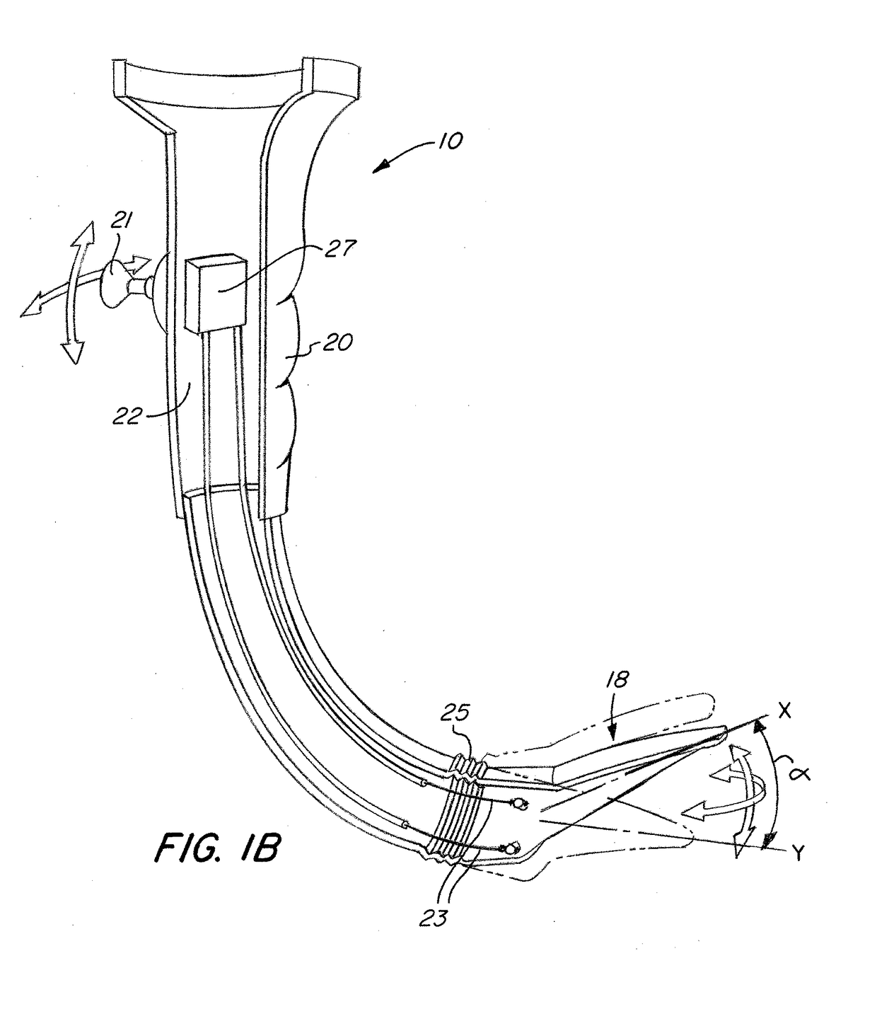
A laryngeal access system includes a laryngeal blade with a proximal portion and a distal portion, an inner channel extending longitudinally through the laryngeal blade, wherein an outer wall of the laryngeal blade has an opening therethrough extending from the proximal portion to the distal portion of the blade through which an object can pass through the outer wall into the inner channel, an articulating member provided at the distal portion of the blade, and an actuator provided at the proximal portion of the blade and coupled to the articulating member, wherein the actuator moves the articulating member from a first position, in which the articulating member has a first longitudinal axis, to a second position, in which the articulating member extends at an angle relative to the first longitudinal axis.

Description

FIELD OF THE INVENTION[0001]The invention relates to a medical intubation device, and more specifically, to a side loading articulating laryngeal access system for performing intubation procedures.BACKGROUND OF THE INVENTION[0002]In critically injured, ill or anesthetized patients, it is often necessary to insert an endotracheal tube into a person's airway to facilitate ventilation of the lungs and to prevent the possibility of asphyxiation or airway obstruction. The most common routes of inserting the endotracheal tube are oral, in which the tube is passed through the mouth and larynx into the trachea, and nasal, wherein the tube is passed through the nose and larynx into the trachea.[0003]The insertion of the endotracheal tube often involves serious risks, such as damage to the vocal cords and a prolonged intubation procedure in which the patients breathing is stopped, but oxygen is not yet delivered to the patient as the tube has not yet been inserted. It is estimated that about ...

Claims


Application Information

Patent Timeline
IPC IPC(8): A61B1/267A61B1/012A61B5/0205A61B1/04A61B5/1455
CPCA61B1/267A61B1/04A61B5/14551A61B5/021A61B1/012A61B5/024A61B5/02055A61B5/6847A61B1/00082A61B1/0052A61B1/0055A61B1/0056A61B1/0057A61B1/05A61B1/0607A61B1/0676A61B1/0684A61B1/00042
Inventor GERRANS, LAWRENCE J.
Owner SANOVAS
Learn More