Vehicle wheel spoke connection

a technology of fiber reinforced spokes and vehicle wheels, which is applied in the direction of spoked wheels, transportation and packaging, and rolling resistance optimization, can solve the problems of increasing the weight of the wheel assembly, poor vibration-damping characteristics, and the steel spokes of conventional bicycle wheels are quite heavy, so as to achieve equal or greater tensile strength, improve vibration-damping characteristics, and improve performance

Active Publication Date: 2017-05-18
SCHLANGER RAPHAEL
View PDF11 Cites 5 Cited by
  • Summary
  • Abstract
  • Description
  • Claims
  • Application Information

AI Technical Summary

Benefits of technology

[0030]The present invention obtains many advantages. One advantage of the present invention is the ability to utilize lightweight materials for the spoke while minimizing the cost and expense of the completed assembly.
[0031]The present invention may be readily adapted to lightweight fibrous spoke reinforcement fibers, such as carbon fiber, aramid fiber (such as Kevlar®), LCP (liquid crystal fiber such as Vectran®), PBO (polyphenylenebenzobisoxasole fiber such as Zylon®), polyethylene fiber (such as Spectra®) and the like. These fibers are impregnated within a matrix to create a spoke and / or tensile element that has a significant performance improvement over the steel spokes they commonly replace. In comparison with the steel wire commonly used in spoke construction, these fiber reinforced materials have equivalent or greater tensile strength than the steel spoke at a much lower density. This allows for the construction of a much lighter spoke and a lighter wheel. Further, these materials have significantly better vibration-damping characteristics than steel to reduce the vibration experienced by the rider and to provide greater rider comfort and control. Still further, these materials also have excellent tensile fatigue properties to reduce or even eliminate spoke failures due to fatigue.
[0032]The embodiments described herein are highly effective at transmitting tensile loads between the spoke and the bracing element and may be designed to provide a structural connection that may be as strong or stronger than the spoke itself. The embodiments described herein are highly effective at producing a lightweight and high-performance vehicle wheel at an economical cost.
[0033]Further features of the present invention will become apparent from considering the drawings and ensuing description.

Problems solved by technology

However, the steel spokes of conventional bicycle wheels are quite heavy and add significant weight to the wheel assembly.
In addition to their excessive weight, steel bicycle spokes have poor vibration-damping characteristics and tend to be very efficient at transmitting road vibration to the rider.
By transmitting vibration, rather than absorbing it, the conventional steel-spoke bicycle wheel lacks in rider comfort and control.
This causes the stress in the spoke to increase and makes the wheel more prone to spoke failure due to fatigue.
However, when attempting to utilize them as spokes in bicycle wheel construction, these fibrous materials are far more difficult to efficiently couple or terminate than their conventional steel-wire counterparts.
In the few cases where these high strength spokes have successfully been utilized in bicycle wheels, their cost and complexity has been very great.
In the case where thermoset matrix resins are utilized, this results in very long molding cycles because the fiber must be carefully layed up and the resin needs long residence time in the mold in order to catalyze and harden.
Also, since the entire spoke is molded, the corresponding mold tool is very large and expensive.
Further, since the cycle times are slow, a large number of these tools are required in order to achieve sufficient production throughput.

Method used


Image

  • Vehicle wheel spoke connection
  • Vehicle wheel spoke connection
  • Vehicle wheel spoke connection

Examples


Embodiment Construction

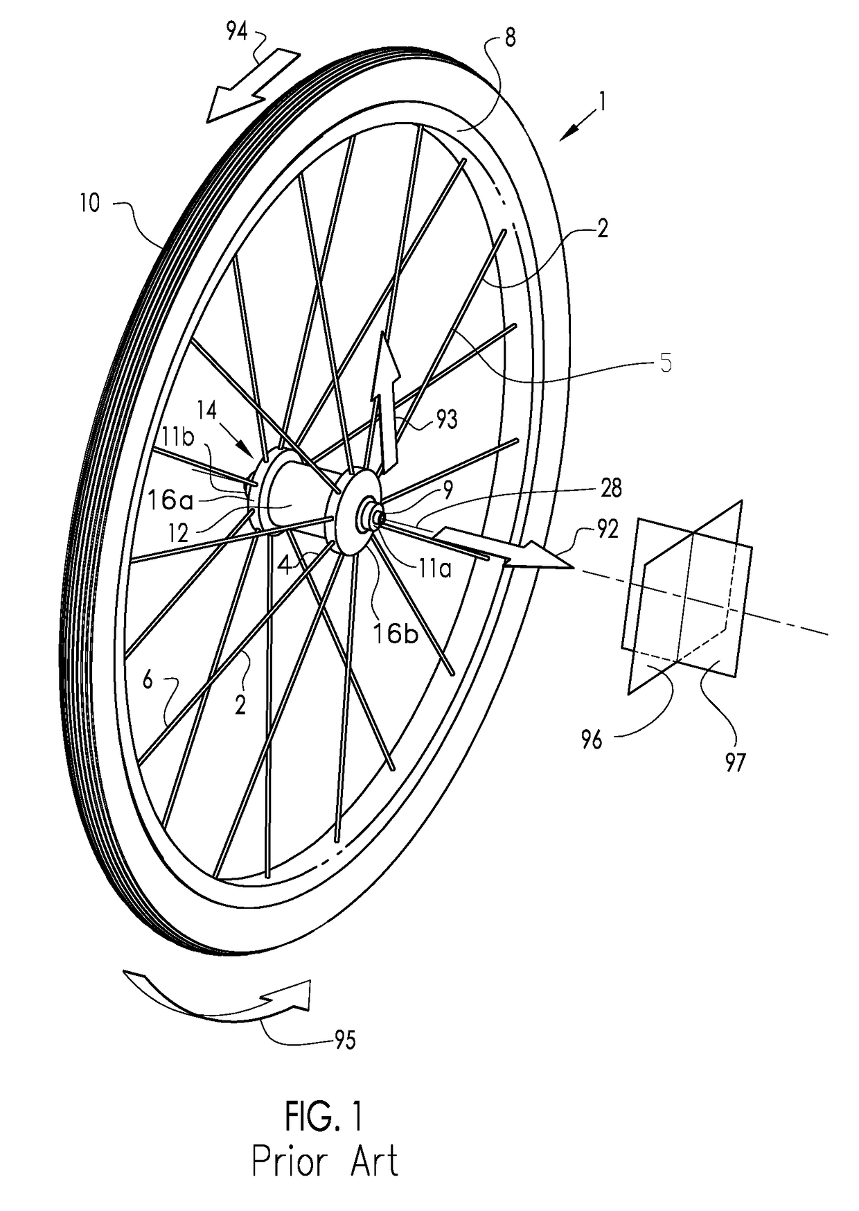
[0094]FIG. 1 describes the basic configuration of an exemplary prior art vehicle wheel, in particular, a bicycle wheel 1, as well as a description of the direction conventions used throughout this disclosure. For clarity, the bicycle frame and the quick release skewer assembly are not shown in this figure. The hub shell 14 is rotatable about the axle 9 and includes at least two axially spaced hub flanges 16a and 16b, each of which include a means for connecting with the spokes 2, with a hub body portion 12 therebetween. Axle 9 includes end faces 11a and 11b that define the spacing of its mounting with the frame (not shown). The axial axis 28 is the axial centerline of rotation of the bicycle wheel 1. The hub flange 16 may be contiguous with the hub shell 14 or it may be separately formed and assembled to the hub body 12 portion of the hub shell 14. The spokes 2 are affixed to the hub flange 16 at their first end 4 and extend to attach the rim 8 at their second end 6. The tire 10 is ...


PUM

PropertyMeasurementUnit
lengthaaaaaaaaaa
tensileaaaaaaaaaa
lengthaaaaaaaaaa

Abstract

A vehicle wheel spoke connection, including: a rim; a hub; a plurality of spokes extending between the rim and hub with a first portion connected to the rim, a second portion opposed to said first portion and connected to the hub, a span portion between the rim and the hub, and an applied tensile load along the span portion; a bracing element including the rim and / or hub. The spoke has a longitudinal axis and is composed of reinforcement fibers in a matrix. The external surface of the spoke includes a pre-formed configured surface comprising a multiplicity of laterally outwardly projecting engagement surfaces that are longitudinally spaced. The spoke is connected to the bracing element by a longitudinal engagement comprising a multiplicity of longitudinally spaced overlie engagements associated with the spoke engagement surfaces. The longitudinal engagement supports the tensile load.

Description

CROSS-REFERENCE TO RELATED APPLICATIONS[0001]This application claims priority of Provisional Patent Application Ser. No. 62 / 289,389, filed Feb. 1, 2016.[0002]This application is also a Continuation-In-Part of U.S. patent application Ser. No. 15 / 412,151, filed Jan. 23, 2017 and is currently pending,[0003]which is a Continuation-In-Part of U.S. patent application Ser. No. 14 / 641,615, filed Mar. 9, 2015 and is currently pending,[0004]which is a Continuation-In-Part of U.S. patent application Ser. No. 12 / 930,643, filed Jan. 13, 2011 and issued as U.S. Pat. No. 8,985,709,[0005]which is a Continuation-In-Part of U.S. patent application Ser. No. 12 / 806,064, filed Aug. 5, 2010 and issued as U.S. Pat. No. 8,657,387,[0006]which is a Continuation-In-Part of U.S. patent application Ser. No. 11 / 879,333, filed Jul. 17, 2007 and issued as U.S. Pat. No. 7,784,878,[0007]which is a Continuation-In-Part of U.S. patent application Ser. No. 10 / 755,653, filed Jan. 12, 2004 and issued as U.S. Pat. No. 7,3...

Claims


Application Information

Patent Timeline
Patent Type & Authority Applications(United States)
IPC IPC(8): B60B1/02B60B1/00B60B1/04
CPCB60B1/0261B60B1/043B60B1/0276B60B1/041B60B1/006B60B2900/311B60B1/003B60B2900/111B60B2900/112B60B2900/115B60B2360/3416B60B1/0246B60B1/0284B60B1/042B60B1/044B60B21/025B60B21/062B60B21/064B60B31/02B60B2310/52B60B2900/131B60B2900/212B60B2900/325B60B2310/50Y02T10/86
Inventor SCHLANGER, RAPHEL
Owner SCHLANGER RAPHAEL
Why Eureka
Try Eureka